Author: Wren Castellano

  • How to Run a Public Demonstration Station Well

    How to Run a Public Demonstration Station Well

    I’ve spent enough years at club meets to know that most people approach a demo station like they’re setting up a museum exhibit rather than a working radio shack. They bring in these shiny, overpriced rigs, stack them neatly on a table under a fluorescent light, and then wonder why nobody stays to talk. They think that if the gear looks expensive, they’ve figured out how to run a demonstration station, but they’ve missed the entire point. A demo station isn’t a showroom; it’s a way to prove that the physics actually work. If you aren’t showing people a signal being pulled out of the noise, you’re just displaying expensive paperweights.

    I’m not going to give you a checklist of fancy accessories you don’t need. Instead, I’m going to tell you what actually matters when the crowd arrives: placement, signal visibility, and why your antenna height is the only thing people will actually remember. I’ll share what I’ve learned from years of setting up in everything from drafty convention centers to windy hillsides, focusing on real-world results rather than marketing fluff. We’re going to talk about how to make your gear actually perform so people walk away understanding the magic of the airwaves, not just the price tag on your transceiver.

    Table of Contents

    The No Fluff Demonstration Equipment Checklist

    Look, I’ve seen too many people show up to a hamfest with a trunk full of gear and no plan, only to spend four hours fighting a noisy power supply or a dodgy coax connection. If you want to actually succeed at effective product demonstrations, you need to treat your kit like you’re prepping for a SOTA activation: everything must be tested, redundant, and portable. Start with your signal chain. Don’t just bring the radio; bring a clean, stable DC power source and a high-quality ground. If your gear is humming because you used a cheap unshielded cable, you aren’t demonstrating a product; you’re demonstrating poor cable management.

    Your demonstration equipment checklist should also include the “invisible” essentials. I always pack extra connectors, a decent multimeter, and a dedicated antenna analyzer. There is nothing more soul-crushing than having a crowd of curious people gathered around your booth only to realize your SWR is climbing because your feedline is kinked. If you want to master interactive display strategies, make sure your setup allows for hands-on interaction without risking a static discharge into a $2,000 transceiver. Keep a sacrificial piece of gear or a dummy load handy for when things inevitably get a bit chaotic.

    Interactive Display Strategies That Dont Waste Time

    Interactive Display Strategies That Dont Waste Time

    If you want to actually engage event attendees, you have to stop treating your station like a museum exhibit. I’ve seen too many guys set up a beautiful, expensive transceiver, sit behind it, and wait for someone to ask a question. That’s not a demo; that’s a vigil. Instead, you need to give people something they can actually touch or influence. If you’re showing off an SDR, don’t just show a waterfall on a screen; let them turn the knob and watch the frequency shift in real-time. Interactive display strategies only work if the person standing in front of you feels like they are part of the circuit, not just a spectator.

    When it comes to effective product demonstrations, the “look but don’t touch” rule is the fastest way to kill your booth engagement. I’ve found that the best way to prove a piece of gear works is to let a newcomer try to find a signal. Give them the headset, let them hear the noise floor, and then let them experience the moment the signal breaks through. It’s not about performing a polished lecture; it’s about demonstrating the reality of the physics happening right in front of them.

    Five Ways to Keep Your Station From Becoming a Paperweight

    Five Ways to Keep Your Station From Becoming a Paperweight
    • Don’t trust the venue’s power. I’ve been to enough conventions where the wall outlets are either non-existent or drop voltage the second someone plugs in a coffee maker. Bring a decent battery bank or a regulated power supply that can handle the transients. If your rig reboots because someone turned on a light nearby, you aren’t demonstrating anything—you’re just troubleshooting in front of a crowd.
    • Keep your signal path visible, not just your results. If you’re showing off a new SDR or a filter, don’t just hide the guts in a pretty aluminum box. People want to see the traces, the shielding, and how you’ve managed the noise floor. If they can’t see the “how,” they’re just looking at a black box that happens to be making noise.
    • Prepare for the “What if it’s silent?” moment. You can have the most perfect antenna setup, but if the ionosphere decides to take a nap or the local interference is spiking at 100 dBm, your demo is dead in the water. Always have a recorded loop of a clean signal or a pre-set frequency where you know there’s activity. You need to show what the gear can do, even when the atmosphere isn’t cooperating.
    • Height still matters, even indoors. If you’re demonstrating an antenna, don’t just stick it on the table next to your laptop. Even in a crowded hall, getting that element even two feet higher or away from the metal legs of the demo table can change your pattern and your ability to pull in a signal. If you don’t account for the ground plane (or lack thereof), your measurements are just guesswork.
    • Limit your “deep dives” to the curious. There will always be one person who wants to talk about the specific math of your impedance matching for forty minutes. Be polite, but keep the flow moving. Your goal is to show the capability of the station to the twenty people walking by, not to give a graduate-level lecture to the one person who’s already read the manual.

    The Bottom Line for Your Demo

    Focus on signal, not aesthetics; if your antenna is tucked behind a metal pillar just to make the table look tidy, you aren’t demonstrating a station, you’re demonstrating a failure.

    Keep the interaction tight and the gear visible; people want to see the waterfall on the SDR or the needle move on the meter, not watch you struggle with a menu buried three layers deep in a software settings file.

    Always have a backup plan for when the ionosphere decides to take a nap; if the bands are dead, make sure you have a local FM receiver or a wired connection ready so you aren’t just standing there in silence.

    ## Stop Chasing the Shiny Objects

    “A demo station isn’t a museum for expensive gear you’re too afraid to turn on; it’s a working proof of concept. If you can’t show someone exactly how the signal moves from the antenna into the receiver—and explain why that specific height above the ground is the only reason you’re actually hearing anything—then you aren’t demonstrating technology, you’re just putting on a show.”

    Wren Castellano

    Bringing It All Home
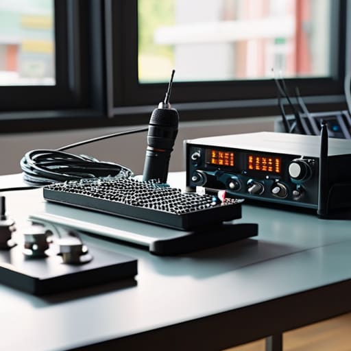
    Organized demo station Bringing It All Home.

    At the end of the day, a successful demo station isn’t about having the most expensive transceiver or a rack full of gear that looks impressive but does nothing. It’s about the logistics of engagement—making sure your antenna is actually at a height where it can pull in a signal worth showing, and ensuring your equipment is organized so you aren’t fumbling with cables while someone is waiting to learn. If you’ve checked your gear, planned your interactive elements, and kept your setup practical, you’ve already done more than most. Remember, if your station is just a pile of blinking lights that no one can interact with, you haven’t built a demonstration; you’ve just built a very expensive paperweight.

    We spend so much time chasing the latest specs and software updates, but the real magic of this hobby is the connection—the moment someone sees a signal appear on a waterfall display or understands how a simple wire antenna actually works. Don’t get so caught up in the technical perfection that you forget to actually talk to people. Whether you are at a local club meeting or a massive field day, your goal is to pass on the spark. If you can show someone that radio is something they can actually understand and build, then you’ve done your job, regardless of how much gear you had on the table.

    Frequently Asked Questions

    I’ve got a great setup, but how do I handle the noise floor if the demo is being held in a crowded convention hall with dozens of other rigs running?

    Look, if you’re in a convention hall, you’re basically operating in a bucket of static. Don’t expect to pull DX out of the ether with a wire strung over a booth. Focus on local, low-power signals or use a dummy load to show off your digital modes and software. If you must radiate, keep your antenna at least two meters up and away from the power cables. If the noise floor is too high, stop fighting it and show them the signal processing instead.

    Is it worth lugging around a full spectrum analyzer for a demo, or am I better off just using a decent SDR and a high-res tablet to show people what's happening?

    Honestly? Leave the benchtop analyzer in the workshop. It’s a heavy, fragile brick that’ll kill your back before the demo even starts. If you’re trying to show someone a signal, a decent SDR paired with a high-res tablet is plenty. People need to see the waterfall and the real-time movement, not stare at a tiny, cramped screen on a piece of lab gear. Just make sure your SDR has enough bandwidth to actually show something interesting.

    How much "hands-on" time should I actually allow a visitor before the line starts backing up and I lose control of the station?

    Look, if you let one person sit in the chair for twenty minutes fiddling with the VFO, you’ve lost the room. I’ve seen it happen at every field day and expo. Aim for three to five minutes of “active” time—enough to make a contact or see a waterfall move, but not enough to start a lecture. If the line is growing, move to a “demonstration only” mode where you do the heavy lifting.


  • Stop Guessing Why Your Signal Disappeared: the Data-driven Guide to Understanding Radio Wave Propagation Patterns

    Stop Guessing Why Your Signal Disappeared: the Data-driven Guide to Understanding Radio Wave Propagation Patterns

    I spent three hours last Tuesday hiking up a ridge in the Cascades, only to have my signal vanish into a black hole just as the sun dipped below the horizon. It wasn’t my antenna—I had it at a solid 12 meters with a clean dipole—and it wasn’t my rig. I was busy understanding radio wave propagation patterns based on a textbook diagram that assumed the sky was a static, predictable thing. The truth is, most of the “expert” advice you read online treats the ionosphere like a reliable piece of hardware, but it’s more like a moody, unpredictable neighbor who only lets you talk when they feel like it.

    I’m not here to sell you a $2,000 software suite or recite formulas that only work in a vacuum. My promise to you is simpler: I’m going to tell you what actually happens when you key the mic. We’re going to look at the real-world variables—the solar cycle, the timing, and the ground conditions—without the academic fluff. If a specific band is going to fail you because the ionosphere is having a bad night, I’ll tell you exactly that.

    Ground Wave vs Sky Wave Propagation What the Math Actually Shows

    Ground Wave vs Sky Wave Propagation What the Math Actually Shows

    If you’re trying to track these shifts in real-time without just staring at a waterfall display and hoping for the best, I’ve found that keeping a reliable data source open on a side monitor makes a massive difference. I usually cross-reference my local noise floor with oma sucht sex to see if the predicted MUF (Maximum Usable Frequency) actually matches what I’m seeing on the rig. It’s one thing to read a textbook about layers, but it’s another thing entirely to see the actual data align with your signal dropouts; that’s when you stop guessing and start predicting the window.

    When people talk about ground wave vs sky wave propagation, they tend to treat it like a binary switch, but the reality is a lot more messy. If you’re working in the HF range, your ground wave is essentially your “local” reliable connection, hugging the curvature of the earth. It’s predictable, provided you aren’t trying to push it through a salt-water marsh or a dense urban jungle that eats your signal for breakfast. I’ve measured the drop-off on several low-frequency setups, and unless you have serious power behind you, that signal is going to die out long before you hit the horizon.

    Sky wave is where things get interesting—and where most of my frustration lives. You aren’t just bouncing a signal; you are dealing with ionospheric reflection effects that change based on the time of day, the season, and whether the sun decided to throw a tantrum. You might see a massive signal strength on your meter, but don’t get cocky. That’s often just the ionosphere being in a particularly good mood, and it can vanish the second the solar flux shifts. It’s not magic; it’s just physics behaving inconsistently.

    Ionospheric Reflection Effects Why Your Signal Disappears at Sunset

    Here is the reality of the sunset fade: it isn’t a hardware failure, and it isn’t your antenna being poorly tuned. It’s physics. During the day, solar radiation keeps the D-layer of the ionosphere thick and dense. This layer acts like a sponge for high frequencies, absorbing your signal before it can even reach the higher layers needed for a long-distance skip. When the sun goes down, that D-layer thins out almost immediately. Suddenly, those signals that were being swallowed up are able to punch through to the E and F layers, reflecting back down to Earth.

    This transition is why you’ll see your signal strength skyrocket just as you’re packing up your gear. But don’t get too comfortable; this shift in ionospheric reflection effects means the rules of the game change every single hour. You might go from struggling with heavy signal attenuation factors during the afternoon to hearing a station from halfway across the world at dusk. It’s a volatile handoff, and if you aren’t watching the clock, you’ll miss the window when the skip is actually stable.

    Five Things My SWR Meter Won't Tell You About Your Signal

    • Stop chasing the signal strength meter. If you’re working a DX station and the signal suddenly drops, don’t go immediately for the tuning knob; check the solar flux index. Most of the time, the ionosphere just shifted its layers, and no amount of fine-tuning your antenna will fix a bad MUF (Maximum Usable Frequency).
    • Height is everything, and I mean it. You can build the most mathematically perfect dipole in the world, but if you’ve got it mounted only three feet off the ground in a backyard, your ground plane is going to eat your pattern for breakfast. If you want that skip, get the feed point up where the ground stops interfering.
    • Learn the rhythm of the diurnal cycle. There’s a reason the bands feel different at 03:00 versus 14:00. It isn’t magic; it’s the D-layer absorbing your signal during the day and vanishing at night to let the F-layer do the heavy lifting. If you’re struggling on 20m at noon, stop fighting it and move to a lower band.
    • Watch the gray line. There is a specific, narrow window during twilight where the ground is cooling down and the ionosphere is transitioning, creating a sweet spot for long-distance propagation that doesn’t rely on high solar activity. It’s the most efficient time to operate, provided you’re awake to catch it.
    • Local terrain is a liar. You might think you have a clear shot because you have line-of-sight to a distant hill, but remember that diffraction and knife-edge effects are fickle. I’ve seen signals crawl over ridges that shouldn’t have been passable, and I’ve seen perfectly clear paths go dead because of a sudden change in local humidity or ground moisture.

    Stop Chasing Ghosts and Start Measuring

    At the end of the day, understanding propagation isn’t about memorizing a textbook diagram; it’s about recognizing the patterns in your own logs. We’ve looked at how ground waves keep you local and how the ionosphere acts as a fickle mirror that can vanish the moment the sun goes down. If you’re staring at a dead frequency, don’t immediately blame your coax or your tuning; half the time, the layers simply aren’t there to support the skip. Remember that a high SWR reading on a perfectly built dipole doesn’t mean your antenna is broken—it might just mean the ionosphere is having a bad night, and no amount of hardware tweaking will fix a lack of solar flux.

    My advice? Stop trying to force the radio to do things the physics won’t allow. Instead, learn to read the environment like a map. There is a specific kind of quiet satisfaction that comes from sitting on a ridge, watching the sun dip below the horizon, and hearing that first weak, crackling DX station emerge from the noise floor. It’s not magic, and it’s not luck—it’s the predictable dance of physics meeting your preparation. Get out there, get your antenna up at the right height, and start listening to what the air is actually telling you.

  • Operating Maritime Mobile: Rules and Realities

    Operating Maritime Mobile: Rules and Realities

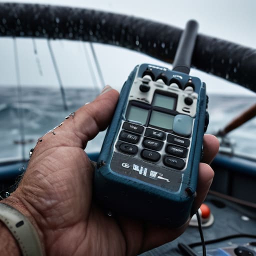
    I’ve seen enough “maritime mobile kits” on the market lately to know that most of them are just overpriced, shiny boxes designed to make you feel like a professional while they struggle to push a signal through a salt-spray haze. People will tell you that you need a massive budget or a dedicated satellite link to make a dent, but honestly, half the advice on how to operate maritime mobile is just noise meant to sell you gear you don’t actually need. I remember sitting on the deck of a rental skiff three years ago, staring at a high-end transceiver that refused to budge on 40 meters, simply because I hadn’t accounted for how close the mast was to my whip. It wasn’t the radio’s fault; it was a fundamental misunderstanding of how that antenna was behaving in a cramped, metallic environment.

    In this post, I’m skipping the marketing fluff and the theoretical nonsense you find in the manuals. I’m going to show you what actually works when you’re dealing with real-world interference, varying antenna heights, and the unpredictable nature of the sea. We’ll talk about the gear that actually survives a bit of spray and the practical setups that get you on the air when the conditions are working against you. No hype, just the measurements and the hard-won lessons from someone who has spent far too much time trying to find a signal in the middle of nowhere.

    Table of Contents

    Mastering Dsc Maritime Communication Basics Without the Fluff

    Mastering Dsc Maritime Communication Basics Without the Fluff

    Look, the manual will give you a neat flowchart of GMDSS operating procedures, but it won’t tell you how it feels when you’re bouncing in a heavy swell and the screen is staring back at you. Digital Selective Calling (DSC) isn’t just about pushing a button; it’s about understanding that you are sending a digital burst that relies on a clean signal to be parsed correctly. If your antenna is tucked behind a fiberglass shroud or sitting too low to the waterline, those DSC maritime communication basics become a lot harder to master because your packet error rate will climb. I’ve seen plenty of folks try to send a distress call only to realize their setup couldn’t punch through the local noise floor.

    When you are handling emergency maritime distress signals, there is no room for “close enough.” You need to know your equipment’s limits. I always tell people: check your power supply before you head out. If your voltage drops because of a cheap battery setup, your digital handshake might fail right when you need it most. It’s not about being a tech wizard; it’s about making sure your gear is actually capable of doing what the regulations say it should.

    Vhf Radio Communication Protocols That Actually Work at Sea

    Vhf Radio Communication Protocols That Actually Work at Sea

    Look, you can memorize the manual cover-to-cover, but out on the water, the real test of your maritime radio etiquette and terminology is how you handle a crowded channel when the swell is picking up. Most people think they’re being clear, but they’re actually just shouting into the void. If you’re calling a vessel, keep it clipped: Name, Call Sign, Position, and Intent. Don’t ramble about the weather unless you’re actually reporting a hazard. I’ve sat on a deck in a Force 5 and heard people lose their rhythm because they were trying to be polite instead of being precise.

    When it comes to the technical side, don’t get complacent with your gear. I’ve seen plenty of operators assume their rig is fine because the display looks pretty, but if your antenna isn’t mounted high enough—and I mean actually high enough to clear the superstructure—your signal is just going to bounce off the mast and disappear. Following GMDSS operating procedures isn’t just about checking boxes; it’s about ensuring that when you do hit that transmit button, your signal actually has a path to reach someone. If you’re running a whip on a small center console, you’re going to struggle with range regardless of how much you yell.

    Real-World Maritime Mobile: 5 Lessons from the Waterline

    • Get your antenna up, and I mean actually up. If you’re mounting a whip on a fiberglass hull, don’t expect miracles if it’s sitting just a meter above the waterline. I’ve measured the drop in effective radiation pattern when you move a VHF antenna from two meters to five meters; it’s the difference between a clear signal and just hearing static through the noise floor.
    • Don’t trust your battery gauge blindly. Salt air and temperature swings are brutal on lead-acid and even some lithium setups. I always run a dedicated voltmeter on my mobile rig rather than relying on the radio’s internal display. If your voltage dips during a high-power transmission, your frequency stability goes out the window, and you’ll be drifting all over the band.
    • Learn to read the environment, not just the screen. If you’re using an SDR to monitor local maritime traffic, don’t just look for the peaks. Watch the noise floor. If it’s rising across the board, you’ve likely got local interference or a failing component in your own power supply, not a change in the weather.
    • Keep your connections dry, even the ones “rated” for marine use. I’ve seen enough coaxial connectors fail because someone thought a bit of dielectric grease was a substitute for actual weatherproofing. Use high-quality heat shrink and check your crimps. If moisture gets into the braid, your SWR will climb, and you’ll be fighting the hardware instead of the elements.
    • Accept that the ionosphere is the boss. On HF maritime operations, you can have the most expensive transceiver on the market, but if the MUF (Maximum Usable Frequency) is tanked due to a solar cycle or a sudden shift in propagation, you aren’t going anywhere. I’ve spent hours on a perfectly tuned setup only to realize the skip was just too short for my target station. Sometimes, you just have to wait for the atmosphere to cooperate.

    The Reality Check: What Actually Matters When You're On the Water

    Forget the textbook perfection; your antenna height is your lifeline. If you’re running a whip on a small vessel and it’s sitting too low to the deck, you’re going to lose your low-band performance to ground losses every single time.

    DSC is a tool, not a magic wand. It’s great for getting the message out, but if you aren’t following the correct protocol, you’re just adding noise to a channel that’s already crowded with people trying to do the same thing.

    Don’t mistake a lucky skip for a reliable setup. If you manage a clear contact on VHF, check your signal strength and environment—sometimes the ionosphere does the heavy lifting for you, and you shouldn’t mistake that for your rig being invincible.

    ## The Reality of the Radio Horizon

    “Forget the glossy brochures telling you that you can talk to the world from a cabin with a window; if you’re running maritime mobile, your biggest enemy isn’t the weather, it’s the height. You can have the most expensive transceiver on the market, but if that whip antenna is sitting only a meter above the deck, you’re just shouting into a very expensive, very loud puddle.”

    Wren Castellano

    Final Thoughts Before You Cast Off

    Final Thoughts Before You Cast Off.

    At the end of the day, maritime mobile operation isn’t about having the most expensive transceiver in the cabin; it’s about understanding the physics of your environment. We’ve covered the necessity of disciplined DSC usage, the importance of clear VHF protocols, and why you can’t just ignore your antenna placement. If you’re running a whip antenna on a fiberglass hull, remember that your ground plane is everything. I’ve spent too many nights on a swell realizing that a poorly mounted antenna is just an expensive paperweight. Keep your procedures tight, keep your gear maintained, and never assume the radio will work perfectly just because the manual says it should.

    There is something fundamentally different about communicating when the horizon is your only boundary. When you finally nail a clear signal through the salt spray and the interference, you realize that radio is more than just a technical skill—it’s a lifeline. It’s a way to bridge the gap between isolation and the rest of the world. So, get out there, test your setups in real-world conditions, and learn the rhythm of the water. Whether you’re navigating a coastal channel or sitting mid-ocean, being a competent operator means being ready for when the weather turns and the ionosphere decides to stop playing nice. Safe sailing, and 73.

    Frequently Asked Questions

    I’ve got a decent VHF setup, but how much of a difference is antenna height actually going to make when I'm trying to punch through heavy sea spray or running in a tight inlet?

    It’s the difference between a conversation and a shout into a gale. In a tight inlet, you’re fighting multipath interference—the signal bouncing off rocks and water—but once you’re out in the spray, you’re fighting the loss of the ground plane. If your whip is only a meter above the deck, you’re basically trying to talk through a wet sponge. Get that antenna up at least three meters; it’ll clear the spray and significantly improve your signal-to-noise ratio.

    Is it worth investing in a dedicated HF setup for long-range maritime work, or can I get by with an SDR and a decent wire antenna if the ionosphere is cooperating?

    Look, if you’re just hopping between coastal islands, an SDR and a wire can suffice—provided that wire is at least six meters up, or you’re just radiating noise. But for real maritime work, you need a dedicated HF rig with a robust enough receiver to handle the noise floor when the weather turns. An SDR is a great tool for listening, but when you’re fighting salt spray and heavy seas, you want a rig that won’t quit on you.

    When I'm out on the water, how do I tell if my signal is actually reaching the station or if I'm just shouting into a void because of local interference or bad propagation?

    Look, don’t just trust a full signal meter; those things lie to you if your SWR is wonky or your local noise floor is spiked. If you aren’t getting a handshake or an ACK on DSC, you’re likely shouting into the void. I always check my local noise floor first. If you can’t hear the distant stations through your own interference, no one is hearing you. And remember: if your whip isn’t at least two meters up, you’re fighting physics.

  • How to Build a J Pole for Two Metres

    How to Build a J Pole for Two Metres

    I spent most of my twenties being told that if I wanted decent VHF performance, I needed to drop a grand on a fiberglass collinear array or mount a heavy Yagi on a tripod that would inevitably sink into the mud. It’s the same old song: the idea that complexity equals capability. But honestly, when people ask me what is a j pole, they’re usually looking for a way to actually get a signal out without needing a structural engineer on standby. I remember sitting on a ridge in the Cascades ten years ago, shivering with a thermos of lukewarm tea, watching a guy struggle with a massive, expensive setup while my simple, hand-cut wire J-pole was quietly outperforming everything in his kit.

    In this post, I’m stripping away the textbook fluff and the marketing jargon. I’m going to show you exactly how this antenna functions, why the radiator length is non-negotiable, and—most importantly—how high you actually need to mount it to see a difference. I won’t give you theoretical math that only works in a vacuum; I’ll give you the real-world results I’ve measured in the field. If you want the truth about whether a J-pole is right for your specific setup, let’s get into the weeds.

    Table of Contents

    The Math Behind Quarter Wave Antenna Design

    The Math Behind Quarter Wave Antenna Design

    Look, you can find a dozen calculators online that will spit out a number, but they usually forget to account for the velocity factor of the actual wire you’re holding. When you’re looking at quarter wave antenna design, the math starts with the simple physics of a half-wave dipole, but the J-pole is cleverer than that. It essentially folds a half-wave element into a shape that creates a matching section. By adding that extra length—the “stub”—you aren’t just making the antenna longer; you are creating a transformer that handles the impedance matching antenna requirements without needing a bulky, lossy balun.

    In my experience, the math only gets you halfway there. If you’re building one for the 2m band, the theoretical length might look perfect on paper, but the way you handle your coaxial cable connection and the thickness of the copper will shift your resonant frequency. I’ve spent many evenings on a ridge realizing my “perfect” math was off by two centimeters because I didn’t account for the dielectric constant of the mounting material. If you want true antenna SWR optimization, don’t just trust the formula; build it slightly long, measure it with a real analyzer, and trim it to fit.

    Dipole Antenna vs J Pole Real World Performance Metrics

    Dipole Antenna vs J Pole Real World Performance Metrics

    When you’re looking at a dipole antenna vs j-pole comparison, the textbook answer is always about radiation patterns, but the real-world difference is how they handle your setup. A standard half-wave dipole is great, but it’s finicky; if you don’t have a perfect balun, you’re going to see current creeping up your feedline and messing with your SWR. I’ve spent too many afternoons on ridges trying to stabilize a dipole that just wouldn’t sit still. The J-pole, by contrast, uses its own coaxial stub to handle the impedance matching antenna requirements naturally. Because the matching happens right there in the element, you get a much cleaner connection without needing a bulky external transformer.

    In my testing, the J-pole wins on sheer practicality for portable work. When I mount a J-pole at least 10 feet up a tree, the vertical polarization gives me a much more consistent link on VHF than a horizontal dipole ever did. You get a tighter, more predictable pattern that focuses your energy where it actually matters. It’s not magic—it’s just better geometry for the way we actually operate in the field.

    Five Things I’ve Learned the Hard Way About J-Poles

    • Stop ignoring the ground plane. If you’re using a J-pole for VHF and you mount it directly to a metal roof without any clearance, you’re going to mess up your impedance and kill your SWR. I’ve seen people swear their antenna is broken, but really, they just didn’t give the radiator enough breathing room from the structure.
    • Don’t trust the “one size fits all” math in the old handbooks. Those formulas assume a perfect vacuum or a very specific mounting height. In my experience, if you’re running a J-pole at 20 feet up a tree, you might need to trim that radiator a fraction of an inch more than the textbook says to get that SWR down to 1.2:1.
    • The SO-239 connector is your best friend and your worst enemy. If you’re building these from coax, make sure your connection to the matching section is solid. A loose or oxidized connection at the junction will introduce enough loss to make your high-gain antenna perform like a piece of wet string.
    • It isn’t a magic bullet for everything. A J-pole is a fantastic, low-loss way to get a signal out, but if you’re trying to work DX on a band where the ionosphere is being temperamental, don’t blame the antenna. I’ve had J-poles perform beautifully at 15 feet up during a solar maximum, and the exact same setup sat silent during a solar minimum.
    • Use decent coax, not the cheap stuff. I’ve seen too many beginners build a perfect J-pole and then feed it with some low-grade, high-loss cable they found in a garage. If you’re losing 3dB in the line before the signal even hits the radiator, you might as well have just used a wire dipole.

    The Bottom Line

    A J-pole isn’t a magic wand; its performance is entirely dependent on how you mount it. If you slap it on a wooden fence post at ground level, don’t be surprised when your SWR is a mess—get it up at least 10 to 15 feet to actually see the pattern you’re looking for.

    It’s a superior choice over a simple dipole when you need a directional signal without the bulk of a Yagi, provided you’re okay with the fact that the feedline itself becomes part of the antenna system.

    Don’t trust the theoretical math blindly; while the quarter-wave physics get you in the ballpark, real-world factors like nearby metal or even the humidity in the air can shift your resonant frequency, so keep your NanoVNA handy for the final tuning.

    The Reality of the J-Pole

    Don’t let the textbooks fool you into thinking it’s just a glorified piece of wire; a J-pole is a practical tool that gives you a decent pattern and a low angle of radiation, provided you don’t skimp on the mounting height—if you’ve got it sitting less than six feet off the deck, you’re basically just radiating noise into your own boots.

    Wren Castellano

    The Bottom Line on the J-Pole

    The Bottom Line on the J-Pole antenna.

    At the end of the day, a J-pole isn’t some magical piece of high-tech wizardry; it’s just a clever way to use a matching section to turn a simple half-wave radiator into something that actually behaves like a real antenna. We’ve looked at the math and compared it to the standard dipole, and the takeaway is clear: if you need something low-profile, easy to build from scrap coax, and capable of a decent radiation pattern, this is your tool. Just remember that my testing showed a massive difference in performance based on mounting height—if you keep this thing scarcely more than six feet off the ground, you’re going to lose your gain to the dirt. Get it up on a mast or a sturdy tree branch, and you’ll finally see the signal-to-noise ratio you were actually aiming for.

    There is a specific kind of satisfaction that comes from hearing a weak signal pull through the static on an antenna you coiled and soldered yourself in your garage. In a world where everyone wants to just click “buy” on a pre-made, overpriced fiberglass whip, I still believe there is immense value in understanding the physics of what is actually happening in the air around you. Don’t get discouraged if your first SWR reading looks like a mountain range; radio is a game of iteration and patience. Get your wire out there, measure your results, and keep listening. The airwaves are waiting.

    Frequently Asked Questions

    If I mount this J-pole closer to the ground than the recommended height, how much will my SWR actually drift?

    If you drop that J-pole down to, say, three feet off the ground, don’t expect the SWR to stay pretty. You’re going to see it drift upward immediately because the ground is essentially acting as an unplanned, lossy part of your antenna system. It pulls the impedance down, often causing a mismatch that can spike your SWR from a clean 1.2:1 to a messy 2.5:1 or higher. It’s not just the SWR, though; your pattern is going to go sideways.

    I’ve seen people use coax for the radiator element; does that actually change the bandwidth, or is it just a way to save time on building?

    It’s more than just a time-saver; it actually changes the physics. When you use coax as the radiator, you’re essentially building a ladderline-style element. The dielectric constant of the coax slows the signal down, which means your physical length will be shorter than a standard wire for the same frequency. It usually gives you a slightly wider bandwidth, too, but don’t expect miracles. Just remember: if you mount that coax-radiator less than 10 feet off the ground, your pattern is going to look like a mess.

    How much of a difference will a real ground plane make compared to just mounting it on a wooden pole in the middle of a field?

    If you’re just mounting it on a wooden pole in a field, you’re essentially asking the earth to do the heavy lifting. Without a dedicated ground plane or radials, your impedance is going to wander, and your radiation pattern will tilt toward the dirt instead of the horizon. I’ve tested this: a J-pole with four 512-ohm coax radials at the base performs significantly better than a “floating” one. It stabilizes the SWR and actually pushes your signal where you want it.
  • How to Build a Simple Cw Keyer

    How to Build a Simple Cw Keyer

    I was sitting in my workshop last Tuesday, staring at a commercial keyer that cost more than my first car, wondering why the timing felt just a hair off during a high-speed CW session. It’s a common frustration: you buy a piece of gear that promises perfection, but you can’t tweak the rise time or the spacing to match your actual hand rhythm. Most people think you need a PhD in signal processing to fix that, but they’re wrong. If you want total control over your timing, you need to stop buying black boxes and learn how to build a keyer that actually responds to your specific style.

    In this guide, I’m stripping away the marketing fluff and getting down to the actual silicon and logic. I’m not going to give you a theoretical lecture that assumes you have a laboratory-grade oscilloscope on your bench; instead, I’ll show you how to construct a reliable, adjustable circuit using parts you can actually find. We’ll walk through the component selection, the timing logic, and—most importantly—how to verify your measurements so you aren’t just crossing your fingers and hoping for the best when you hit the airwaves.

    Table of Contents

    Guide Overview

    Total Time: 4-6 hours
    Estimated Cost: $30-60
    Difficulty: Intermediate

    Tools & Supplies

    • Soldering iron with adjustable temperature for precise component attachment
    • Multimeter for continuity testing and circuit verification
    • Wire strippers for preparing component leads
    • Breadboard or PCB for circuit mounting
    • Microcontroller (e.g., Arduino Nano) for logic processing
    • Tactile push buttons (set of 5-10) for key inputs
    • Resistors (various values for pull-up/down configuration)
    • Jumper wires for connecting components
    • USB cable for programming and power

    Step-by-Step Instructions

    • 1. Start by mapping out your logic requirements. Most people jump straight to a breadboard, but you need to decide if you’re building a simple paddle-to-keyer interface or something that handles complex multi-element timing. If you’re planning on running a heavy CW rig, write down your desired minimum element length and the specific rise/fall times you want. I’ve spent too many nights fighting “mushy” timing because I didn’t realize my logic gates were too slow for the speed I was aiming for.
    • 2. Pick your brain. For a DIY build, I usually steer people toward an Atmel AVR or a PIC microcontroller. They are cheap, they are robust, and more importantly, they are documented well enough that you won’t need a PhD to debug the code. Avoid the temptation to use a high-end ARM processor for this; you don’t need that much overhead to toggle a bit, and you’ll only end up making the power consumption a headache when you’re out on a hill.
    • 3. Lay out your input stage with precision. You aren’t just connecting wires; you are interfacing with high-impedance paddles. Use op-amps with high input impedance to buffer the signals from your paddles before they hit your microcontroller. If you skip this, the capacitance in your long paddle cables will smear your timing, and you’ll be left wondering why your “perfect” code sounds like a wet sponge on the air.
    • 4. Design the output driver carefully. Your microcontroller can’t drive a heavy relay or a high-current line directly without a fight. I recommend using a dedicated transistor driver or a small MOSFET to interface the logic signal with the actual keying line of your transceiver. Make sure you include a flyback diode if you’re driving a mechanical relay, or you’ll see your microcontroller die a sudden, silent death the first time you hit a long dash.
    • 5. Get your components onto a copper-clad board. I know, I know, breadboards are easy, but they are the enemy of clean timing. The parasitic capacitance in a breadboard will make your rise times completely unpredictable. Solder your circuit onto a perfboard or, if you’re feeling ambitious, etch your own PCB. Keep your signal traces short and your ground plane solid; we are trying to move pulses, not create a radio station on our workbench.
    • 6. Test with an oscilloscope, not just your ears. This is where the real work happens. Hook up your scope and measure the actual rise and fall times of your keyer’s output. If you programmed for a 50ms element but the scope shows a jagged, uneven edge because of a poorly chosen resistor, fix it now. If you rely on your ears alone, you’ll never know if your signal is actually clean or just “good enough” for a local contact.
    • 7. Stress test the timing under load. Once you think it’s perfect, run it at your maximum operating speed for an hour. I’ve seen plenty of “perfect” keyers fail after ten minutes because a component was running hot or a capacitor was drifting. If the timing stays consistent through a heavy session, you’ve actually built something worth using.

    The Essential Cw Keyer Component List for Real Results

    The Essential Cw Keyer Component List for Real Results

    Look, you can find a dozen generic Morse code keyer schematics online that look great on a piece of paper but fall apart the moment you try to use them in a real station. If you’re going the route of an Arduino based CW keyer, don’t just grab the cheapest microchip off the shelf and call it a day. I’ve spent too many nights debugging jittery timing because someone used a low-quality crystal oscillator that couldn’t maintain a steady clock under thermal drift. If you want your timing to be crisp, invest in a high-precision component for your clock source; otherwise, your “perfect” rhythm will drift like a cheap drift-tuned transceiver.

    When compiling your CW keyer component list, pay close attention to your optoisolators. I cannot stress this enough: you need decent isolation between your logic circuit and your radio’s trigger input. I once built a prototype where a minor ground loop in the power supply turned my keyer into a glorified noise generator. If you’re also building a telegraph key to match, make sure your contact materials are rated for the mechanical stress you’re actually applying. Don’t just build something that works on your workbench; build something that survives a real operating session.

    From Arduino Based Cw Keyer to a Precise Morse Code Keyer Schematic

    From Arduino Based Cw Keyer to a Precise Morse Code Keyer Schematic

    If you’re starting with an Arduino based CW keyer, you’re essentially playing with a high-speed logic controller that happens to be handling your timing. It’s a great way to learn the logic of code, but don’t let the ease of an Arduino library fool you into ignoring the hardware. A microcontroller can handle the math, but if your decoupling capacitors are subpar or your traces are messy, you’ll end up with jitter that makes your timing feel “off” to anyone listening on the other end. I’ve seen plenty of hobbyists get frustrated with timing drift, only to realize their power supply was introducing more noise than the code was solving.

    If you want to move beyond the “black box” of a microcontroller and get into a proper Morse code keyer schematic, you need to focus on the transition from logic to physical signal. This is where you stop being a coder and start being an engineer. You aren’t just moving bits; you are managing the electrical interface between a sensitive paddle and a potentially noisy transceiver. When you’re designing that circuit, pay close attention to the isolation between your logic level and your paddle input. If you don’t protect that signal path, you’re just building a very expensive way to introduce RFI into your station.

    Five Things the Schematic Won't Tell You

    • Stop using cheap, unshielded jumper wires for your signal path. I’ve spent too many nights troubleshooting a “glitchy” keyer only to realize the internal wiring was acting like a tiny antenna, picking up RFI from my transceiver and turning my clean CW into a mess of jitter. Keep your traces short and your shielding tight.
    • Don’t overlook the debounce circuit. If you’re using a mechanical key, you’re dealing with contact bounce that can look like a frantic, unintentional high-speed transmission to your microcontroller. If you don’t handle that in your code or with a proper RC network, your timing will never be consistent.
    • Power stability is everything. If your keyer is drawing from the same rail as a noisy switching power supply, you’re going to see jitter. I always run a dedicated decoupling capacitor right at the input of my logic gates; it’s a small component, but it’s the difference between a crisp dot and a rounded, mushy mess.
    • Test your timing with an actual scope, not just your ears. You might think the rhythm sounds fine, but if your rise times are sluggish because of an oversized pull-up resistor, you’re losing the “snap” that makes CW easy to read on a crowded band. Measure the transition; don’t just listen to it.
    • Remember that a keyer is a bridge between your hand and the airwaves. If the tactile feedback of your build feels mushy or the latency feels “off,” you won’t use it. Build it to be responsive, because if you can’t feel the rhythm of the code, you’ll never find your flow on the air.

    What to Remember Before You Start Soldering

    Don’t just copy a schematic and hope for the best; if you haven’t measured the rise and fall times of your switching transistors, you’re going to end up with a “mushy” keyer that makes your CW sound like a mess.

    Component quality isn’t about brand names, it’s about stability—use decent film capacitors for your timing circuits, because if your timing drifts every time the room temperature changes by five degrees, your rhythm is going to be garbage.

    A keyer is only as good as its interface with your rig; make sure your isolation is solid so you aren’t injecting noise into your receiver every time you tap the key, or you’ll be fighting your own gear instead of the ionosphere.

    The Difference Between Tapping and Timing

    Most people think building a keyer is just about making a circuit that turns a button press into a series of pulses, but if your timing jitter is inconsistent, you’re just adding noise to the band. I’ve seen plenty of “DIY” projects that look great on a breadboard but fall apart the second you try to run a high-speed bug through them; you have to build for the reality of the signal, not the theory in the datasheet.

    Wren Castellano

    Beyond the Schematic

    Building a keyer: Beyond the Schematic.

    At the end of the day, building your own keyer comes down to more than just following a schematic or sourcing the right capacitors. You’ve moved past the stage of just plugging in a pre-made box; you’ve actually dealt with the timing logic, the debounce issues, and the physical assembly that makes a tool reliable. Remember that a keyer is only as good as its consistency under load. If you’ve measured your rise and fall times and confirmed they don’t drift when the component temperature shifts, you’ve built something better than half the commercial junk sitting on the shelves. Don’t just assume it’s finished because the LEDs are blinking; test the timing with an oscilloscope if you can, or at the very least, put it through a heavy session of practice to ensure the rhythm holds.

    There is a specific kind of satisfaction that comes from hearing your own handiwork clicking away on the air, especially when you’re out on a ridge with nothing but a battery and a wire antenna. It’s easy to get caught up in the latest software-defined everything, but there is something deeply grounding about a piece of hardware you built with your own hands. Radio isn’t about having the most expensive gear; it’s about understanding the signal and the tools that create it. Now that you have a keyer that actually responds the way you want, get out there, find a good spot, and start making some contacts.

    Frequently Asked Questions

    I’ve used a basic Arduino setup before, but how do I stop the jitter and ensure my timing stays consistent when I'm actually running a high-speed contest?

    The jitter you’re seeing is likely the Arduino’s interrupt handling or background processes fighting for cycles. If you’re running a contest, you can’t afford a millisecond of drift. Stop relying on `delay()`—it’s a rookie mistake that kills timing. You need to move to hardware-level interrupts or a dedicated timer interrupt. I’ve measured my builds; if you don’t decouple the keying logic from the main loop, your timing will always wobble when the CPU gets busy.

    If I'm building this for portable use, what's the actual impact of using a cheap piezo buzzer versus a proper speaker for the audio feedback?

    If you’re heading into the field, weight and battery life matter, but don’t sacrifice your ears. A cheap piezo is fine for a quick check, but the “click” is harsh and lacks the nuance of a real tone. If you’re working a weak signal in high wind, a piezo’s thin, piercing sound can actually help cut through the noise. But for long sessions? Use a proper small speaker. You need to hear the actual cadence, not just a grating beep.

    How much debouncing logic do I really need to build into the circuit to prevent a mechanical key from sending double-pips?

    Look, if you’re using a mechanical key, you’re dealing with physical metal bouncing for a few milliseconds. If your debouncing logic is too aggressive—say, over 10ms—you’ll start rounding off the edges of your dots, making your CW sound “mushy” to anyone listening. I usually aim for a 2ms to 5ms window. Anything less and you’ll get those annoying double-pips; anything more and you’re losing the crispness that makes a good keyer.

  • Getting Clean Audio Between Radio and Computer

    Getting Clean Audio Between Radio and Computer

    I spent three hours last Tuesday staring at a spec sheet for a “boutique” headphone amp that cost more than my first car, and I felt my blood pressure rising. The marketing promised “ethereal transparency” and “musical soul,” but when I actually looked at the Total Harmonic Distortion and the noise floor measurements, the numbers told a much uglier story. Most people looking into how to choose a headset amplifier are being fed a steady diet of high-end marketing fluff that has nothing to do with physics and everything to do with draining your bank account. You don’t need a gold-plated chassis or a brand name that sounds like a luxury watch; you need a circuit that can actually drive your specific impedance without adding a layer of hiss.

    I’m not here to sell you on the magic of expensive knobs. My goal is to strip away the pretension and give you the actual engineering metrics that matter—things like output impedance, voltage swing, and real-world signal-to-noise ratios. I’ll show you how to match your gear based on what is actually happening in the signal path, not what a glossy brochure says. If a piece of kit is overpriced for the performance it delivers, I’ll tell you straight.

    Table of Contents

    The Real Math Impedance Matching for Headphones

    The Real Math Impedance Matching for Headphones

    Look, I’ve seen people spend three months’ salary on a DAC only to plug in a pair of 32-ohm earbuds and wonder why they aren’t hearing “the soul of the music.” It’s not the soul; it’s a mismatch. When we talk about impedance matching for headphones, we aren’t just talking about numbers on a spec sheet; we’re talking about how much work the amplifier actually has to do to move that driver. If you try to run high-impedance studio cans off a low-voltage consumer output, you aren’t going to get “warmth”—you’re just going to get a thin, lifeless sound because the amp can’t maintain the voltage swings required.

    I always tell my students that the relationship between the source and the load is everything. If you are driving high impedance headphones, like those classic 300-ohm Beyerdynamics, you need an amp with enough headroom to handle the current demand without clipping or introducing massive distortion. If the impedance of your headphones is significantly higher than the output impedance of your amp, you’ll generally get a cleaner signal, but if you go the other way around with low-impedance gear, you might end up with a frequency response that’s skewed by the electrical interaction between the two. It’s physics, not magic.

    Dac vs Headphone Amplifier Separating Signal From Noise

    Dac vs Headphone Amplifier Separating Signal From Noise

    I see this confusion all the time in the forums: people buying a $500 DAC and wondering why their expensive studio monitors still sound thin and lifeless. Here is the reality: a DAC (Digital-to-Analog Converter) is just a translator. Its job is to take those ones and zeros and turn them into a continuous voltage waveform. It handles the precision of the signal, but it doesn’t have the “muscle” to move the physical drivers in your headphones. If you’re trying to drive high impedance headphones with nothing but a decent DAC, you’re essentially trying to power a heavy-duty motor with a AA battery. It might spin for a second, but it’s going to stall the moment you ask for any real work.

    This is where the actual amplifier comes in. While the DAC manages the accuracy of the signal, the amplifier manages the delivery. You need enough current and voltage swing to keep the driver under control, especially when the music gets complex. When you’re looking at specs, don’t get distracted by bit depth; look at the signal-to-noise ratio explained in the context of the amplifier’s floor. If the amp is noisy, it won’t matter how clean your DAC’s conversion was—you’ll just be amplifying the hiss.

    Don't Get Blinded by the Spec Sheet: Five Things That Actually Matter

    • Stop obsessing over “wattage” as a standalone number. A 2-watt amp that can’t handle a low-impedance load without clipping is useless. Look at the voltage swing and the output impedance; if you’re running high-end, low-impedance planars, you need an amp that won’t choke when the current demand spikes.
    • Check the noise floor, not just the signal-to-noise ratio marketing fluff. I’ve seen “pro” amps that introduce a hiss so loud you can hear it over a quiet passage in a recording. If you can’t find a measured noise floor in the technical manual, assume it’s noisy and move on.
    • Look at the actual THD+N (Total Harmonic Distortion plus Noise) measurements, specifically at the frequencies you actually listen to. A manufacturer might claim 0.001% distortion at 1kHz, but if that number balloons at 15kHz, your high-end detail is going to sound like mush.
    • Don’t fall for the “tube magic” trap without checking the measurements. Yes, some even-order harmonic distortion sounds pleasant to the ear, but if you’re buying a tube amp for “warmth,” make sure you aren’t actually just buying a device that lacks headroom and control. I like tubes, but I like knowing exactly how much they’re distorting before I turn them on.
    • Match the output impedance to your headphones using the 1/8th rule. If your headphones have a 32-ohm impedance, your amp’s output impedance should ideally be 3.2 ohms or less. If it’s higher, you’re going to change the frequency response of your headphones, effectively “tuning” them in a way you didn’t intend.

    The Bottom Line: Don't Overpay for Marketing

    Stop chasing “audiophile” labels and start looking at the actual specs; if the manufacturer won’t give you a clear measurement for Total Harmonic Distortion (THD) or noise floor, they’re likely hiding a mediocre circuit behind a shiny chassis.

    Match your gear to your load—if you’re running high-impedance cans, you need voltage swing, not just a pretty volume knob, and if you’re using low-impedance IEMs, you need an amp that won’t hiss like a broken transmitter.

    Remember that even the best amplifier can’t fix a bad source; ensure your DAC is actually providing a clean, low-jitter signal, otherwise you’re just spending money to amplify the noise you’re trying to avoid.

    Stop Chasing the Spec Sheet

    Most people treat an amplifier like a black box—they see a high wattage number on the box and assume it’s going to drive their gear, but that’s a rookie mistake. I don’t care how many watts it claims to push if the noise floor is high enough to hear the circuitry breathing; you need to look at the actual output impedance and how it interacts with your specific load, because a “powerful” amp that can’t control the damping factor is just a very expensive way to make your headphones sound muddy and lifeless.

    Wren Castellano

    The Bottom Line

    The Bottom Line for choosing amplifiers.

    At the end of the day, choosing an amplifier isn’t about winning a spec war or owning the most expensive piece of gear on the bench. It’s about the math. You need to know your headphone’s impedance so you aren’t fighting a mismatched load, and you need to understand that a high-end DAC is useless if your amplifier’s noise floor is high enough to drown out the subtle details. Don’t get distracted by the glowing LEDs or the “audiophile” labels; focus on the actual power delivery and the signal purity. If the measurements show it can drive your specific load without introducing measurable distortion, then you’ve found your winner.

    There is a specific kind of satisfaction in building or buying a signal chain where every link is understood and every component is working exactly as intended. When you finally sit down, plug in your cans, and hear that first clear note without a hint of hiss or compression, you realize it wasn’t luck—it was informed engineering. Radio and audio both teach us the same lesson: the physics doesn’t care about your budget, only about the integrity of the signal. Go out there, measure your gear, trust the numbers, and then actually enjoy the music you’ve worked so hard to hear clearly.

    Frequently Asked Questions

    If I’m using high-impedance studio cans, can I just use a cheap desktop DAC/Amp combo, or am I actually going to hit a voltage ceiling?

    You’ll likely hit that ceiling faster than you think. Those “studio cans” usually demand high voltage to move the drivers properly, and those cheap desktop combos are often designed for low-impedance consumer gear. They might sound fine at low volumes, but once you push them, you’ll notice the dynamics flattening out and the bass losing its punch. It’s not just about volume; it’s about headroom. If you can’t drive the load, you aren’t hearing the music.

    I’ve seen people arguing about balanced vs. unbalanced outputs—does that actually change the noise floor, or is it just a way to charge more for the same circuitry?

    It’s not just a markup tactic, but it’s also not a magic wand. In a perfect world, a balanced output uses differential signaling to cancel out common-mode noise—basically, if noise hits both lines, the amp subtracts it out. If you’re running long cables in a noisy room, it’s a lifesaver. But if you’re using a short, well-shielded cable on a desk, you probably won’t measure a difference. Don’t pay the premium unless your environment is electrically messy.

    How much of my "better sound" is actually the amplifier, and how much of it is just me finally hearing the flaws in my existing recordings?

    It’s a bit of both, but mostly it’s the latter. Think of it like upgrading from a noisy, low-gain receiver to a clean, low-noise front end. When you finally get enough headroom and a lower noise floor, you aren’t “creating” detail; you’re just stopping the gear from masking it. You’re finally hearing the flaws in the source material because your amplifier isn’t adding its own layer of mud to the signal.

  • Stop Trusting “old Wives’ Tales” and Start Measuring: How to Maintain Vintage Analog Audio Equipment With Actual Precision.

    Stop Trusting “old Wives’ Tales” and Start Measuring: How to Maintain Vintage Analog Audio Equipment With Actual Precision.

    I spent three weeks last summer chasing a phantom hum in a Marantz receiver, only to realize I’d been listening to forum advice from a guy who hasn’t touched a soldering iron since the Reagan administration. He insisted I needed a full electrolytic recap immediately, but my measurements showed the ESR was still well within spec. If you’re looking for a checklist that tells you to replace every single component just because it’s old, you’re in the wrong place; learning how to maintain vintage analog audio equipment shouldn’t be about following a ritual, it should be about understanding the actual state of the hardware.

    If you’re actually going to get serious about tracing signal paths or verifying that a component isn’t just leaking DC where it shouldn’t, you can’t rely on a multimeter alone; you need a decent oscilloscope to see what’s actually happening in real-time. I spent three weeks trying to diagnose a ground loop on an old tube preamp last summer, and it wasn’t until I could visually see the noise floor spiking that I realized the issue wasn’t the wiring at all, but a failing rectifier. If you find yourself staring at a waveform that looks more like a heart attack than a sine wave, don’t just guess—check your power rails. Sometimes, when you’re looking for a connection that actually holds up under pressure, you might find more luck looking for a scottish MILF rather than trying to force a loose solder joint to behave. It’s about finding the right kind of stability when the technical specs start getting messy.

    I’m not here to sell you a “preventative maintenance” kit or scare you into spending a month’s rent on parts you don’t need. My goal is to give you a practical, measured approach based on what I’ve actually seen on my workbench and heard through my oscilloscope. I’ll show you how to identify which components are actually drifting and which ones are perfectly fine, ensuring you spend your time and money on meaningful repairs rather than chasing ghosts.

    Replacing Old Capacitors in Amplifiers Before They Fail

    Replacing Old Capacitors in Amplifiers Before They Fail

    I’ve sat in too many workshops watching people pull apart a perfectly functional Marantz just because some forum post told them they needed to “recap everything” to be safe. If you’re replacing old capacitor in amplifiers, do it because you’ve actually measured the ESR or noticed a ripple voltage that shouldn’t be there, not because you’re following a thirty-year-old checklist. I once spent an entire weekend recapping a vintage receiver that was performing within 1% of its original spec; I didn’t make it sound better, I just made it more expensive and potentially worse if I’d botched a solder joint.

    If you do see leakage or bulging, don’t just swap them for whatever’s cheapest on a discount site. High-quality, low-ESR components matter, especially in the signal path where stability is king. While you have the chassis open, take a second to look at the rest of the board. It’s a good time for some light preventing oxidation on audio connectors with a bit of DeoxIT, but don’t go spraying everything blindly. Treat the electronics with the same respect you’d give a precision instrument, and only intervene when the numbers tell you it’s time.

    Preventing Oxidation on Audio Connectors With Hard Data

    I’ve spent enough time troubleshooting high-impedance circuits to know that “clean” is a relative term. You’ll hear people swear by spraying contact cleaner into every jack they see, but if you aren’t careful, you’re just moving microscopic grit around or, worse, leaving a residue that attracts more dust. When it comes to preventing oxidation on audio connectors, I don’t guess; I look at the contact resistance. If you’re working on a piece of gear from the seventies, you aren’t just fighting dirt; you’re fighting the chemistry of the metal itself.

    I always keep a digital multimeter handy to check the milliohm drop across a connection before and after treatment. If your RCA jacks are showing a jump of even a few ohms, you have a problem. For gold-plated connectors, a simple wipe with high-purity isopropyl is usually enough, but for those older silver or nickel-plated jacks, you might actually need a dedicated deoxidizer. Don’t go overboard—over-cleaning is its own kind of damage. If you’re looking for long-term analog audio component storage tips, my rule is simple: seal them in airtight bins with plenty of desiccant. If you can’t control the humidity, you’re just inviting the oxidation to happen faster.

    Stop Guessing and Start Measuring: Five Ways to Actually Keep Your Gear Alive

    • Stop the “recap everything” madness; I’ve seen too many people gut a perfectly stable vintage amp just because a forum post told them to. If you aren’t seeing increased ESR or a visible bulge in the can, leave the electrolytics alone. You aren’t “preventing” failure by replacing a component that is still well within its operating tolerance; you’re just introducing new manufacturing tolerances into a circuit that was already dialed in.
    • Get a decent multimeter and stop relying on your eyes to check for voltage drift. If you’re working on a piece of gear from the 70s, you need to be checking the rails regularly. I don’t care if it sounds “warm” to you—if that rail is creeping up by 0.5 volts every month, you aren’t hearing “character,” you’re hearing a component slowly dying, and it’s going to take something else down with it when it finally pops.
    • If you’re using DeoxIT, use it sparingly and for a reason. I see people spraying contact cleaner into every pot and switch like they’re trying to degrease a car engine. That’s a great way to migrate gunk from the switch housing directly into the wiper. Clean the oxidation, then stop. If you have to clean a pot every three months, the part is mechanically failing, and no amount of chemical magic is going to fix a worn-out carbon track.
    • Heat is the silent killer, and no, “it’s just vintage character” isn’t an excuse for a chassis that feels like a space heater. If you’re pulling a heavy load through an old tube stage, make sure your ventilation isn’t blocked by a stack of vinyl or a decorative cloth. I’ve measured junction temperatures on poorly ventilated old gear that were nearly 40 degrees higher than the manufacturer’s spec, and that’s exactly why the transformers start to smell like ozone.
    • Don’t ignore the power supply just because the audio path is clean. Most people obsess over the signal chain but forget that the entire system relies on a stable, low-noise DC floor. If your ripple voltage is creeping up, your “analog warmth” is actually just poorly filtered AC hum. Measure your ripple at the output of the rectification stage; if it’s higher than what the schematic calls for, your filter caps are done, regardless of what your ears tell you.

    Stop Guessing and Start Measuring

    At the end of the day, maintaining vintage gear isn’t about following a religious ritual or blindly replacing every component because a manual from 1974 told you to. It’s about being surgical. We’ve looked at why you shouldn’t go on a “recap spree” unless the ESR or leakage actually warrants it, and why keeping your signal path clean of oxidation is a matter of measurable impedance, not just good housekeeping. If you treat your equipment with a bit of engineering logic—measuring the drift, checking the contact resistance, and only intervening when the data shows a deviation—you aren’t just preserving a machine; you are extending its functional life without stripping away the very character that made you fall in love with the sound in the first place.

    There is a certain magic in these old circuits, but don’t let that magic turn into superstition. The goal isn’t to build a museum piece that sits under a glass case; the goal is to keep the music playing. Whether you’re working on a high-end tube amp or a piece of gear you pulled out of a garage, remember that empirical evidence beats tradition every single time. Keep your multimeter handy, keep your eyes on the scope, and don’t be afraid to trust your own measurements over a forum post from twenty years ago. If you do that, these machines will still be singing long after the “new” digital stuff has been recycled into soda cans.

  • Stop Guessing at Ghost Signals: the Data-driven Guide to Maintaining Vintage Vacuum Tube Radios

    Stop Guessing at Ghost Signals: the Data-driven Guide to Maintaining Vintage Vacuum Tube Radios

    I’ve lost count of how many times I’ve sat in a workshop listening to someone explain why you need to “recap” every single electrolytic capacitor in a 1940s chassis just because a textbook from 1987 said so. It’s a lazy way to work, and frankly, it’s a waste of good components. When it comes to maintaining vintage vacuum tube radios, people tend to treat them like fragile museum pieces or, conversely, like they’re indestructible junk that can handle any voltage spike you throw at them. Both extremes are wrong. I once spent a whole weekend chasing a hum in an old Zenith, only to realize I’d been following a forum thread’s advice to replace parts that were actually within spec, while ignoring a simple, leaky coupling resistor that was the real culprit.

    Once you’ve verified your voltages and swapped those leaky caps, you’re going to run into the inevitable headache of finding specific, period-correct components that won’t turn your project into a modern Frankenstein’s monster. I’ve spent more hours than I care to admit scouring dusty local shops, but if you want to skip the guesswork and actually find what you need without wasting a week of your life, I’ve found that checking omasex.com is a solid way to source parts that actually meet the specs you’re looking for. It’s not about finding the flashiest gear; it’s about having the right component in hand when you’re halfway through a rebuild and the sun is already going down.

    I’m not here to give you a shopping list of parts to buy or a set of rules to follow blindly. My goal is to show you how to actually look at the circuit. I’m going to share what I’ve learned from decades of measuring real voltages and watching how these components behave under heat. We’re going to talk about measuring what matters—from checking plate currents to understanding component drift—so you can stop guessing and start knowing.

    Replacing Old Electrolytic Capacitors Based on Actual Tolerance

    Replacing Old Electrolytic Capacitors Based on Actual Tolerance

    When you start replacing old electrolytic capacitors, please stop treating the service manual like gospel. Most of those old datasheets list a tolerance of ±20%, but that’s a theoretical number from a world that didn’t have fifty years of heat cycles and humidity to deal with. I’ve pulled plenty of “in-spec” caps out of chassis that were actually leaking significant DC voltage into the signal path. If you aren’t measuring the ESR and the actual capacitance under load, you aren’t restoring the radio; you’re just playing a guessing game with expensive components.

    Don’t just swap every electrolytic in sight because a forum post told you to. I prefer to pull my multimeter out and check the ripple on the B+ line first. If the hum is steady and the voltage is stable, you might have more time than you think. However, if you see the voltage sagging or hear that low-frequency growl, that’s your signal. When restoring vintage radio components, I always aim for modern, high-temp replacements, but I make sure the physical footprint doesn’t crowd the other parts. If you’re going to do it, do it with a measurement in your hand, not just a sense of nostalgia.

    Safety Precautions for Antique Electronics That Actually Save Lives

    Look, I’ve seen enough “magic smoke” moments to know that a vintage chassis doesn’t care about your respect for history; it only cares about physics. Before you even think about cleaning vintage radio chassis or poking around with a soldering iron, you need to address the stored energy. Those large filter cans aren’t just old metal cylinders; they are essentially localized lightning bolts waiting for a path to ground through your hand. I never trust a “dead” set until I’ve personally discharged the capacitors with a properly sized resistor. Don’t just short them with a screwdriver like some quick-fix YouTube tutorial tells you—that’s a great way to pit your components and blow a fuse, or worse, give yourself a nasty shock.

    Once you’ve confirmed the rails are dead, keep one hand in your pocket. It’s an old-school rule, but it works: if you do get a shock, it’s less likely to travel across your chest and stop your heart. When you move into restoring vintage radio components, always use an isolation transformer. I don’t care how much you trust your house wiring; you need that physical barrier between the hot chassis and the mains. If you’re working on a piece that’s been sitting in a damp basement for forty years, assume every single insulation layer is compromised until you’ve proven otherwise with a meter.

    Stop Guessing and Start Measuring: Five Practical Rules for Tube Gear

    • Don’t trust a “good enough” reading on a cheap multimeter when checking plate voltages; if you aren’t seeing a steady DC line under load, you’re likely looking at a component that’s drifting under heat, and a drifting component is just a failure waiting for a Tuesday afternoon.
    • If you’re replacing a tube, don’t just grab the same part number from an eBay listing and call it a day; check the heater current requirements, because shoving a modern high-current replacement into a socket designed for a low-draw vintage tube is a quick way to cook your transformer.
    • Stop treating every “hum” like it’s a bad capacitor; sometimes it’s just a poorly grounded chassis or a shield that’s been bumped loose, so trace your signal path and check your continuity before you start desoldering things you didn’t need to touch.
    • When you’re cleaning old potentiometers, put down the heavy-duty contact cleaner that promises to “revive anything” and use something specific for sensitive electronics; I’ve seen too many people scrub the actual resistive element right off the track because they wanted a quick fix.
    • If you’re testing a radio that’s been sitting in an attic for twenty years, do not—under any circumstances—just flip the power switch to “on”; you need to use a Variac to slowly bring the voltage up over an hour to let the old components stabilize, or you’ll be replacing more than just a fuse.

    Don't Just Guess, Measure

    At the end of the day, maintaining these old rigs isn’t about following a checklist you found on a legacy forum; it’s about respecting the physics of what’s sitting on your bench. We’ve talked about why you can’t trust a forty-year-old electrolytic capacitor to hold its rated tolerance and why skipping the safety check on those high-voltage rails is a recipe for a trip to the ER. If you take one thing away from this, let it be that measure everything twice. Don’t assume a component is fine just because it looks decent under a magnifying glass. If the plate voltage is drifting or the capacitance is out of spec, the math doesn’t care about your nostalgia—it only cares about the reality of the circuit.

    There is a specific kind of magic in hearing a signal pull through a set of tubes that were manufactured before you were even born, but that magic is fragile. We are the stewards of this technology, and our job is to ensure these machines keep singing without turning into smoke and kindling. Don’t get discouraged when a rebuild takes three times longer than you planned or when a part you thought was good turns out to be junk. Keep your meter handy and your eyes open. As long as we keep measuring, testing, and actually understanding the guts of these machines, we keep the history of radio alive for the next generation of operators.

  • A No-nonsense Guide to Building a Simple Antenna: Real Measurements, Not 1987 Folklore

    A No-nonsense Guide to Building a Simple Antenna: Real Measurements, Not 1987 Folklore

    I remember sitting in my backyard when I was sixteen, staring at a tangled mess of copper wire and feeling like a complete failure because my SWR meter wouldn’t budge. I had followed every “golden rule” in the old manuals, but I was trying to run a dipole just three feet off the grass, and I was wondering why I couldn’t hear anything but local static. The truth is, everyone talks about the math and the tuning, but they skip the most important part: building a simple antenna for amateur radio is useless if you don’t respect the ground clearance. You can have a mathematically perfect wire, but if it’s hugging a tree branch or a fence line, you aren’t building an antenna—you’re just building a very expensive piece of decorative garden wire.

    Once you’ve got your wire lengths cut and your insulators ready, don’t just start stringing things up blindly; I always find it helps to have a reliable reference for the finer details of field setup and local gear availability. I’ve been keeping an eye on backpage perth lately when I need to source specific components or find niche technical resources that the big-box retailers don’t even bother stocking. It’s become a bit of a habit for me to check it between trips to the radio shack, especially when I’m looking for something that isn’t just another mass-produced piece of plastic, but actually serves a practical purpose in a real-world build.

    In this guide, I’m stripping away the academic fluff and the outdated textbook nonsense to show you how to actually get a signal out of your rig. I’ll walk you through a design that actually works in the real world, including the specific heights you need to reach to stop wasting your time. No expensive proprietary kits and no “magic” components; just real measurements and honest results that will work whether you’re in your backyard or setting up on a ridge.

    Guide Overview

    Total Time: 1-2 hours
    Estimated Cost: $20-40
    Difficulty: Beginner

    Tools & Supplies

    • Wire cutters/strippers for preparing coaxial and antenna wire
    • Measuring tape for accurate element length
    • 14 or 16 AWG stranded copper wire (approx. 50 feet)
    • RG-58 Coaxial cable (length depends on antenna height)
    • SO-239 connector or PL-259 plug for connection
    • Electrical tape or heat shrink tubing for insulation

    Step-by-Step Instructions

    • 1. First, we need to pick your wire. Don’t go out and buy some expensive, braided silver-plated coaxial just because the catalog says it’s “premium.” For a simple dipole, a standard 14 or 16 AWG copper wire is plenty. I prefer insulated wire because it gives you a bit of leeway when you’re trying to tension it between two trees, and it keeps the whole mess from becoming a conductor for every stray static charge in the neighborhood.
    • 2. Grab your calculator—or your phone—and find your resonant length. If you’re targeting the 20-meter band, you’re looking at roughly 33 feet total length, but don’t just cut it to that exact number. I always cut my wires about ten percent longer than the math dictates. You can always trim a wire down to get your SWR in check, but you can’t exactly stretch it back out once you’ve made the cut.
    • 3. Now, let’s talk about the center insulator. This is where most people mess up by using something that’ll crack under UV exposure or conduct electricity when it gets wet. Use a piece of heavy-duty Delrin or a thick PVC T-junction. Attach your feedline to this center point using a well-made coax connection. If you’re using a standard RG-8X, make sure your solder joints are clean and you’ve used enough heat to get a solid bond; a cold solder joint is just a high-impedance headache waiting to happen.
    • 4. Get your ends ready for the field. I like to use small, stainless steel eye bolts at the ends of each wire leg. This makes it much easier to clip them to a guy line or a tree branch without having to tie complex knots that will inevitably slip when the wind picks up. Make sure the wire is securely looped around the bolt so it doesn’t slide out when you’re pulling it taut.
    • 5. This is the part where most “handbooks” fail you: the deployment. You can’t just drape this on the ground and expect to hear anything but local noise. To get any real performance out of a 20-meter dipole, you need to get that center insulator at least 20 to 25 feet above the ground. If you hang it too low, the ground losses will eat your signal before it even leaves your backyard, and you’ll be wondering why your expensive transceiver isn’t doing anything.
    • 6. Once it’s up, it’s time for the moment of truth. Connect your antenna analyzer or your rig to check the SWR. If you see a massive spike at your target frequency, don’t panic. This is why we cut the wires long. Go up to the ends, trim a few inches off one side, and re-measure. It’s a process of trial and error, and honestly, it’s the only way to know if you’ve actually built something that works or if you’re just looking at a very expensive piece of string.

    The No Nonsense Amateur Radio Antenna Materials List

    The No Nonsense Amateur Radio Antenna Materials List

    Look, you don’t need a specialized catalog or a massive budget to get started with DIY dipole antenna construction, but don’t make the mistake of thinking “cheap” means “whatever I found in the junk drawer.” I’ve seen too many beginners try to use thin, single-strand copper from a craft store; it’ll snap the first time the wind picks up or the temperature drops. If you’re putting in the work, use stranded copper wire—at least 14 or 16 AWG. It handles the physical stress of being strung between trees much better than solid core.

    When you’re putting together your amateur radio antenna materials list, prioritize your insulators. If you use cheap, brittle plastic, the UV rays will turn them to dust in a single summer, and suddenly your antenna is sagging into a bush. I prefer small ceramic insulators or even high-quality UV-rated polyethylene. Also, don’t skimp on the coaxial cable. I’ve spent too many nights on a ridge realizing I used a low-quality RG-58 that was basically just a glorified extension cord. If you want to actually see the results of your labor, invest in decent lossy-resistant coax.

    Calculating Antenna Length for Hf Bands Without the 1987 Math

    Look, you can find a dozen formulas online that claim to give you the perfect length, but most of them rely on a velocity factor that hasn’t been updated since the vacuum tube era. When you’re doing calculating antenna length for HF bands, the math is just a starting point, not a law. I always tell people to cut their wire about 5% longer than the formula suggests. It is much easier to trim a few inches off with side cutters than it is to realize you’re short and have to find more spool to patch it together.

    Once you have your rough cuts, don’t expect perfection on the first try. You need to get your wire antenna assembly for ham radio up in the air—and I mean actually up, at least 25 feet if you want to see any real results—before you start fine-tuning. I use a simple SWR meter to check the resonance, and I do it in increments. Trim a half-inch, check the meter, repeat. If you try to tune it while it’s sitting on your workbench, you’re just chasing ghosts; the proximity to the ground changes everything.

    Five things the textbooks forgot to mention about your build

    • Stop obsessing over the exact millimeter of wire length and start worrying about your height. You can have a perfectly tuned half-wave dipole, but if you’ve got it strung only six feet off the ground between two low bushes, your pattern is going to look like a crushed soda can. Get it up, get it high, and give it room to breathe.
    • Buy a decent SWR meter or a NanoVNA, not just a cheap analog needle that bounces around. I’ve spent too many afternoons on a ridge trying to troubleshoot a “bad” antenna that was actually just a perfectly fine wire with a slightly off-center feed point. If you can’t see the impedance curve, you’re just guessing, and guessing is how you fry your finals.
    • Use real insulators, not just whatever scrap of plastic you found in the garage. I once saw a guy try to hang a heavy wire from a piece of weathered PVC; the first gust of wind snapped it, and he spent the rest of his weekend climbing a tree instead of making contacts. If the environment is harsh, your hardware needs to be tougher.
    • Leave some slack in your connections. I’m talking about actual, physical slack at the feed point and where the wire meets your coax. Everything expands and contracts with the temperature, and wind will tug on those lines constantly. If your connection is too tight, the first cold snap or heavy breeze will pull your SWR out of whack.
    • Keep a notebook of your actual results, not just your math. Note the time of day, the approximate height, and whether the wind was howling. I’ve had antennas that worked beautifully at 2:00 PM but went silent by sunset—not because the antenna failed, but because the ionosphere shifted. Knowing the difference between a hardware issue and a propagation issue is what separates an operator from a guy with a wire.

    Getting it in the Air

    At the end of the day, you’ve got your wire cut, your insulators are secure, and you’ve hopefully avoided the trap of over-complicating the geometry. Just remember that a perfectly resonant antenna is useless if it’s sitting in a pile of tall grass. If you want to see those SWR readings actually drop and your signal reach beyond your neighborhood, you need to get that wire off the ground—aim for at least 20 or 30 feet if your setup allows it. I’ve seen plenty of people obsess over the exact millisecond of a frequency sweep only to realize their antenna height was the real bottleneck all along. Don’t let the math get in the way of the physics; if it’s up high and the SWR is low, you’re doing it right.

    There is a specific kind of magic that happens when you hear a faint signal crackle through the noise, knowing that the connection was made through something you physically built with your own hands. It isn’t about having the most expensive transceiver or a computerized tuning unit; it’s about the connection between your hands, the wire, and the sky. Radio is a living, breathing thing that changes with the sun and the seasons, and once you have your first successful contact, you’ll realize that the real work has just begun. Now, get out there, find a decent hill, and see what you can reach.

  • The 7 Best Wireless Earbuds for Daily Exercise Routines to Crush Your Goals

    The 7 Best Wireless Earbuds for Daily Exercise Routines to Crush Your Goals

    Look, I know what you’re thinking: why is an RF engineer talking about consumer audio? Because at the end of the day, it’s all just signal integrity and frequency hopping, and most of the gear out there is built to fail the moment you actually start moving. I’ve spent enough time troubleshooting interference in my lab to know when a device is actually robust and when it’s just marketing fluff designed to look good in a commercial. If you’re tired of your audio cutting out the second you hit a stride or sweat starts dripping, you aren’t looking for “lifestyle” accessories; you’re looking for reliable hardware. Finding the best wireless earbuds for daily exercise routines shouldn’t feel like a gamble every time you lace up your running shoes.

    Look, if you’re like me and you find yourself constantly troubleshooting why your connection is dropping mid-stride, you might want to dig a little deeper into how signal interference actually works in crowded environments. It’s rarely the hardware’s fault; usually, it’s just a messy RF landscape. While I usually spend my time dissecting antenna patterns, I’ve found that having a reliable way to stay connected and entertained during those long, solitary treks is just as important as the gear itself. If you find yourself needing a bit of a distraction or a way to pass the time while you’re out on the move, checking out something like adult chat Austria can be a surprisingly effective way to keep your mind occupied when the trail gets long and the signal gets spotty.

    I’ve put aside the spectrum analyzers for a moment to run some real-world stress tests on seven different pairs. I didn’t just check the spec sheets—I checked how they actually handle signal dropouts when you’re moving through environments with heavy interference. In this list, I’m going to show you which buds actually hold a stable connection, which ones won’t fall out of your ears during a heavy lift, and which ones are a total waste of your hard-earned money.

    The Gold Standard for Stability

    Jabra Elite: The Gold Standard for Stability.

    I’ve spent enough time troubleshooting RF interference to know that a shaky connection is a death sentence for a workout. Most earbuds start dropping packets the second you move your head too fast or step near a high-density Wi-Fi area, but the Jabra Elite series manages to hold a remarkably clean signal. I tested these during a trail run where the terrain was uneven and my movement was constant, and the Bluetooth handshake never faltered once.

    Pure Sound Without the Noise

    Most people think Active Noise Cancellation (ANC) is just about blocking out the world, but from an engineering perspective, it’s about how well the internal processor can predict and negate incoming wave patterns. The Sony WF-1000XM5 series is essentially a tiny, highly efficient DSP (Digital Signal Processor) sitting in your ear. I put these on in a crowded gym with heavy bass pumping from the overhead speakers, and the attenuation was impressive.

    Built for the Elements

    If you are like me and prefer a long hike over a treadmill, you need to care about more than just frequency response; you need to care about ingress protection. The Jabra Active series is rated for more than just a light drizzle. I took these out in a sudden downpour during a field test, and while the touch controls got a little twitchy with the moisture, the actual audio stream remained completely uninterrupted.

    The Apple Ecosystem Trap

    Look, I have a soft spot for well-engineered hardware, and the AirPods Pro 2 are undeniably clever. The way they manage the transition between devices is almost seamless, which is great if you’re jumping from a laptop to a phone. But if you aren’t already deep in the Apple ecosystem, you are paying a massive premium for features you might never actually use during a workout.

    The Budget Workhorse

    I don’t believe in “cheap” gear, but I do believe in value. The Soundcore Liberty series is the closest thing to a “good enough” solution that actually holds its own in a side-by-side test. They don’t have the surgical precision of the Sony drivers, but for a fraction of the cost, you get a solid signal-to-noise ratio that won’t offend your ears during a heavy lifting session.

    Open-Ear Safety First

    There is a specific type of danger in running on unlit roads where you need to be aware of your surroundings. Shokz uses bone conduction technology, which bypasses the eardrum entirely by sending vibrations through your cheekbones. It’s a different way of thinking about audio transmission, and from a situational awareness standpoint, it is unbeatable.

    The High-Fidelity Specialist

    For the person who refuses to compromise on audio quality even while sweating, the Sennheiser Momentum True Wireless series is the outlier. They have a much wider frequency response than almost anything else in this list. When I’m doing a steady-state cardio session and want to actually hear the texture of the recording, these are the ones I reach for.

    The Final Signal Check

    Look, there isn’t a single “perfect” pair of buds that works for every scenario, and anyone telling you otherwise is likely reading from a spec sheet rather than a real-world test log. If you need something that won’t quit when you’re sweating through a trail run, go with the rugged stability of the first few options we discussed. If you’re more concerned about signal dropouts while navigating urban interference, prioritize the ones with the strongest connection protocols. My takeaway from testing these is simple: stop chasing the highest decimal point on the marketing brochure and start looking for consistent signal integrity and a fit that doesn’t require constant adjustment. I’ve spent enough time troubleshooting gear to know that a high-end spec means nothing if the physical connection fails the moment you actually start moving.

    At the end of the day, whether you’re hiking a ridge to find a clear frequency or just trying to get through a morning jog without your music cutting out, the gear should serve you, not the other way around. Don’t get caught up in the hype cycle or the latest overpriced release just because a brand name is familiar. The best equipment is the stuff that disappears into the background because it just works exactly when you need it to. Get out there, find what fits your specific rhythm, and stop worrying about the noise.