
I was halfway up a ridge in the Catskills, shivering in a light drizzle, when my transceiver started acting like a possessed toy. I’d checked the connections twice, but as soon as I keyed the mic, the voltage at the rig tanked, leaving me with nothing but a digital readout of failure and a very quiet radio. Most people will tell you that if you just buy a “heavy-duty” power supply, you’re set, but that’s a lie. If you want to learn how to build a station power distribution system that actually survives a heavy duty cycle, you have to stop looking at the labels on the box and start looking at your voltage drops.
In this guide, I’m stripping away the marketing fluff and the outdated diagrams from manuals written before I was born. I’m going to show you how to calculate your wire gauge based on real-world resistance, how to select busbars that won’t become a bottleneck, and why your grounding strategy is just as important as the copper itself. We aren’t just plugging things into a strip; we are building a reliable backbone for your station. I’ll give you the numbers I use in my own shack, so you can stop guessing and start operating.
Table of Contents
- Step-by-Step Instructions
- The Truth About Wire Gauge Selection for Dc and Real Voltage Drop Calculati
- Mastering Busbar Configuration for Power and Proper Overcurrent Protection
- Five Things the Manuals Won't Tell You About Your Power Setup
- The Bottom Line: Don't Build It Based on "What Usually Works"
- ## The Cost of Cheap Copper
- Final Checks and Moving Forward
- Frequently Asked Questions
Guide Overview
Tools & Supplies
- Multimeter for testing continuity and voltage
- Wire strippers for preparing conductor ends
- Screwdriver set for terminal connections
- Drill for mounting the enclosure
- Power distribution block (1 unit)
- Electrical enclosure box (1 unit)
- Gauge-appropriate copper wire (various lengths)
- Circuit breakers or fuses (set of 3-5)
- Cable glands for strain relief (2-4 units)
- Terminal blocks and connectors (1 pack)
Step-by-Step Instructions
- 1. Start by mapping your actual current draw, not the “peak” numbers printed on the back of your radio’s manual. Those numbers are usually optimistic marketing fluff. I sat down with my multimeter and a spreadsheet last month to track exactly what my rig, my preamp, and my cooling fans pull during a heavy SSB session. You need to know your true maximum continuous current so you aren’t sizing your cables based on a theoretical maximum that never actually happens.
- 2. Choose your bus bar or distribution block based on physical space and heat dissipation. Don’t just grab the cheapest screw-terminal block from the hardware store; if you’re running high current, you want something with enough surface area to keep from getting hot. I prefer heavy-duty bus bars that allow me to see every connection clearly. If you can’t see the connection, you can’t tell if it’s oxidizing or loosening over time.
- 3. Select your wire gauge with an eye on voltage drop, not just ampacity. This is where most people trip up. You might see a wire rated for 30 amps and think it’s fine for a 20-amp load, but if that wire is running ten feet from your battery to your radio, that voltage drop will kill your transceiver’s performance when the sun goes down. I always over-spec my wire by at least one size to ensure my gear sees a rock-solid 13.8V, even when the heavy lifting starts.
- 4. Use high-quality, crimped connections rather than cheap twist-on terminals or, heaven forbid, solder joints that look like a bird’s nest. I use a proper ratcheting crimper and heat-shrink tubing on every single terminal. A cold solder joint might look pretty, but under the vibration of a portable setup or the thermal cycling of a hot shack, it’s a recipe for intermittent failure that will drive you mad during a contest.
- 5. Install dedicated fusing for every single branch of your distribution system. Do not, under any circumstances, rely on a single master fuse for the entire shack. If a regulator fails in your linear amplifier, you want that specific fuse to pop instantly, rather than letting a surge travel back through your entire bus and fry your expensive SDR or your computer interface.
- 6. Implement a common ground point, but keep your RF ground and your DC power ground conceptually separate in your mind. I run all my power returns back to a single, heavy-duty copper bus bar. This prevents ground loops that introduce hum into your audio, but you need to make sure that bus is physically bonded to your station ground to keep the static from building up.
- 7. Label everything. I know, it sounds tedious, but when you’re troubleshooting a station at 2:00 AM during a solar flare, you don’t want to be playing a guessing game with a multimeter. Use a label maker or even just some neat masking tape to mark which fuse controls which piece of gear. Clarity is a tool, just like a calibrated oscilloscope, and it’s one you’ll thank yourself for later.
The Truth About Wire Gauge Selection for Dc and Real Voltage Drop Calculati

Look, I’ve seen too many people pull a wire straight out of a generic “recommended” chart and wonder why their transceiver is resetting the moment they key the PTT. The problem is that most charts assume a perfect world with zero temperature fluctuation and negligible distance. When you’re doing wire gauge selection for DC, you have to account for the reality of your specific run. If you’re running a high-current line from a battery bank to a heavy-duty amplifier, a tiny fraction of a volt might not seem like much on a multimeter, but that cumulative loss is what kills your efficiency and causes your rig to brown out during a heavy SSB call.
Don’t just eyeball it. I always run my own voltage drop calculations before I even touch my crimpers. I factor in the total length of the loop—not just the one-way distance—and I assume the worst-case scenario for resistance. If you’re building a serious setup, I’d rather have a wire that is slightly too thick than one that’s just barely “within spec.” It’s much better to have a little extra copper than to spend your evening troubleshooting a phantom ground loop or a fluctuating supply.
Mastering Busbar Configuration for Power and Proper Overcurrent Protection
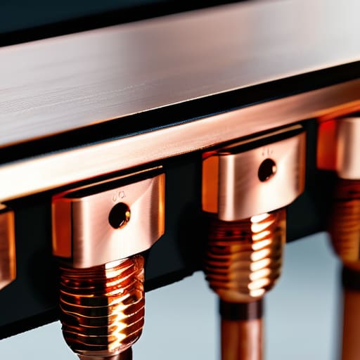
Once you’ve sorted your wire gauge selection for DC, you have to decide how that power actually reaches your gear. I’ve seen too many setups where someone runs a single, massive cable to a cheap, multi-tap strip that looks like it belongs in a model train set. That’s a recipe for noise and failure. Instead, I recommend a dedicated busbar configuration for power that separates your high-current paths from your sensitive logic circuits. If you’re building a serious power distribution unit assembly, use solid copper busbars mounted on insulators. It keeps the physical connections tight and minimizes the resistance that eats your voltage before it even reaches the radio.
When it comes to overcurrent protection methods, please stop relying on the tiny fuses that come in the back of the transceiver. Those are for protecting the radio, not your station. You need to implement proper circuit breaker sizing at the source. I prefer using high-quality, resettable breakers or heavy-duty fuses right at the main bus. If a short occurs in a long run of coax or a faulty power supply, you want that breaker to trip instantly, not wait for the wire to turn red. Measure your trip points; don’t just guess based on a label.
Five Things the Manuals Won't Tell You About Your Power Setup
- Stop relying on “rule of thumb” fuse ratings; if you’re running a high-current SDR or a high-power linear amp, your fuse needs to be sized for the actual trip-point of your specific hardware, not just a generic number you found in a 1980s textbook.
- Keep your RF-heavy gear and your sensitive logic-heavy gear on separate branches of the busbar; I’ve seen too many people try to run a transceiver and a cheap computer off the same unshielded line only to wonder why their screen is full of digital noise every time they key the mic.
- Grounding is not a suggestion, but it isn’t a magic wand either; connect your power distribution chassis to a single-point ground to prevent ground loops, and for heaven’s sake, don’t assume a nearby copper pipe is a “good enough” ground for your RF return.
- Check your terminal connections after the first hour of heavy operating; heat causes expansion, and if you haven’t torqued those lugs properly, you’ll find a high-resistance connection that’s eating your voltage and turning your power supply into a space heater.
- Always build in a “test point” or a spare breaker slot; I learned this the hard way when I tried to add a new tuner to a system that was already maxed out, and I spent three hours re-wiring the whole distribution block instead of just clicking in a new module.
The Bottom Line: Don't Build It Based on "What Usually Works"
Stop eyeballing your wire gauge; if you haven’t actually calculated your voltage drop for the specific length of your run, you’re just gambling with your rig’s stability.
A tidy busbar isn’t about looking professional—it’s about reducing resistance and making sure your overcurrent protection is actually positioned to protect the wire, not just the radio.
If your station starts acting up during a high-duty cycle transmission, don’t assume the radio is broken; go back and check if your power distribution can actually handle the real-world load you’re pulling.
## The Cost of Cheap Copper
“You can spend all day obsessing over the latest SDR or a high-end transceiver, but if you’re running your station through undersized wire and a handful of unrated terminals, you aren’t building a radio station—you’re building a fire hazard. I’ve seen more rigs die from a slow voltage sag during a heavy transmit cycle than from actual component failure. Measure your drops, buy the gauge you actually need, and stop assuming the manufacturer’s ‘recommended’ specs account for the heat you’re actually going to generate.”
Wren Castellano
Final Checks and Moving Forward
At the end of the day, a reliable station isn’t built on hand-wavy assumptions or “close enough” math. You’ve done the work: you calculated your actual voltage drops instead of relying on a generic chart, you selected wire gauges that won’t turn into heaters under load, and you laid out a busbar system that actually makes sense for your specific rig layout. Remember, if you skip the overcurrent protection or try to save a few bucks by using undersized copper, you aren’t just risking a blown fuse—you’re risking the stability of your entire signal path. A solid power foundation means when the propagation is finally perfect, you won’t be staring at a flickering display or a dropping voltage regulator; you’ll be focused on the signal.
There is a particular kind of satisfaction that comes from flipping the master switch and watching your gear settle into a steady, clean operating state. It’s not just about the hardware; it’s about the confidence to operate knowing that every connection and every millivolt is exactly where it ought to be. Radio is a demanding hobby, and the physics of electricity don’t care about your intentions, only your implementation. Build it right, measure it twice, and then get out there and find someone on the other side of the world.
Frequently Asked Questions
If I’m running a high-power linear amplifier that pulls serious current, should I be looking at a dedicated busbar just for the RF gear, or can I run it off my main distribution block?
If that linear is pulling serious current, give it its own dedicated busbar. I’ve seen too many setups where a high-draw amp creates enough voltage sag to make the transceiver’s logic circuits act twitchy or reset mid-transmission. You don’t want your rig’s CPU fighting for scraps every time you key the pedal. Run a heavy-gauge trunk to a dedicated block for the RF gear; it keeps the noise floor lower and the voltage steady.
I’ve seen people using cheap automotive-style fuse blocks for their stations; are those actually reliable enough for long-term indoor use, or am I asking for a fire?
If you’re using those cheap, plastic automotive fuse blocks, you’re essentially gambling with your gear. They’re designed for vibrations in a truck, not the constant, steady thermal load of a station running for hours. I’ve seen the terminals on those things oxidize or loosen just enough to create a high-resistance point. That heat builds up, melts the plastic, and suddenly you’ve got a fire hazard instead of a radio shack. Get a proper, industrial-grade terminal block or a dedicated power distribution unit. Don’t skimp where the heat lives.
How much "headroom" should I actually build into my power supply capacity if I plan on adding an SDR setup or some extra cooling fans down the road?
Look, don’t just add 20% because a manual told you to. If you’re planning on an SDR and some extra fans, I aim for at least 50% headroom. An SDR might not pull much, but those cooling fans can kick in right when your rig hits peak modulation, and I’ve seen plenty of setups sag exactly when the signal needs to be strongest. Measure your peak current draws, then build for the worst-case scenario.
