I spent three hours last Tuesday staring at an LCR meter, wondering why the filter I’d built for my portable setup was drifting like a loose wire in a gale. I had followed the schematic to the letter, but my readings were all over the place. The problem wasn’t the math; it was the fact that I’d been treating the winding process like a craft project rather than a precision task. Most people think learning how to wind an inductor is just about wrapping wire around a core until it looks tidy, but if your turns aren’t tight and uniform, your inductance is going to drift, and you’ll be chasing phantom readings all night.
In this guide, I’m stripping away the textbook fluff to show you how to actually get consistent results. I won’t give you a lecture on Maxwell’s equations, but I will show you how to manage tension, how to choose the right core for your specific frequency, and why your winding technique matters more than the fancy kit you bought. We’re going to focus on repeatable, measurable success so that when you finally head out to the hills, your gear actually does what you designed it to do.
Table of Contents
- Step-by-Step Instructions
- Beyond the Calculating Inductance Formula Why Math Isnt Enough
- Mastering Winding Tension and Precision for Real World Performance
- Five Things Your Textbook Forgot About Real-World Inductance
- The Real-World Summary
- The Gap Between Theory and Reality
- The Reality of the Final Turn
- Frequently Asked Questions
Guide Overview
Tools & Supplies
- Mandrel or cylindrical object to wrap around
- Wire cutters or side cutters to trim ends
- Magnet wire (enameled copper wire) 1 roll
- Form (PVC pipe, cardboard tube, or bolt) 1 unit
Step-by-Step Instructions
- 1. Grab your core and your wire, but before you even think about winding, get your measurements straight. Don’t just eyeball the number of turns; if you’re aiming for a specific inductance, you need to know your wire gauge and your core’s permeability to the decimal. I’ve spent too many nights staring at a meter because I assumed I knew the value instead of actually calculating it first.
- 2. Start by cleaning your core. It sounds trivial, but if there’s any dust, oil from your skin, or old residue on that ferrite, your turns won’t sit flush. If the wire isn’t making consistent, tight contact with the surface, you’re going to end up with air gaps that mess with your coupling and turn your precision inductor into a random number generator.
- 3. Secure your starting lead. I like to use a small piece of high-quality Kapton tape to anchor the first loop of wire to the core. Don’t just wrap it around loosely; you want that first turn to be rock solid. If the start of your coil is slipping or shifting, every single measurement you take afterward is going to be a lie.
- 4. Now, begin the winding process, and this is where people usually trip up: maintain constant tension. As you wrap, keep the wire taut. If you let it go slack, the turns will settle differently under heat or vibration, and your inductance will drift. I don’t care how “pretty” it looks; if it’s loose, it’s junk.
- 5. Keep your turns uniform and side-by-side. You aren’t making a decorative spool for a craft project; you’re building a component. If you start overlapping wires or creating uneven gaps, you’re changing the effective geometry of the inductor. I’ve seen plenty of “successful” builds fail the moment they hit a higher frequency because the winding wasn’t tight enough to handle the parasitic capacitance.
- 6. Once you hit your target number of turns, don’t just call it a day. Stop, clean your hands, and measure it with your LCR meter. I know, I know—you did the math, you counted the turns, you think you’re done. But the math is a theory; the meter is the reality. If you’re off by more than a few percent, you need to add or subtract turns right then and there before you seal the thing up.
- 7. Secure the finished coil with a layer of varnish or a specialized coating. This isn’t just for neatness; it’s to ensure that once the component is in a circuit, nothing moves. Vibrations from a cooling fan or even thermal expansion can shift those wires just enough to change your tuning. If it isn’t stabilized, it isn’t finished.
Beyond the Calculating Inductance Formula Why Math Isnt Enough
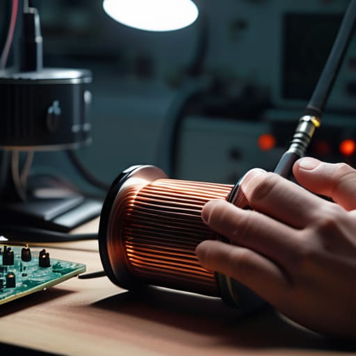
Look, the calculating inductance formula is a fine starting point, but if you treat it like gospel, you’re going to end up with a component that works perfectly on your simulator and fails miserably on your workbench. Math assumes a world of perfect geometry and ideal conditions, but real physics is much more temperamental. You can follow every textbook instruction to the letter, but if your winding tension and precision are inconsistent, you’re going to see your inductance drift every time the temperature in the room changes by five degrees. I’ve spent too many nights troubleshooting a filter that wouldn’t settle, only to realize I’d wound the coils a little too loosely, creating air gaps that the math simply didn’t account for.
It’s also about the physical reality of your components. You might pick the right magnetic core materials on paper, but if you haven’t considered how the heat from the current affects the core’s permeability, you’re just building a ticking clock. Don’t forget that wire gauge selection for coils isn’t just about preventing the wire from melting; it’s about skin effect and how that current actually moves through the conductor at higher frequencies. If you ignore the physical nuances, you aren’t building a circuit—you’re just making a very expensive way to generate heat.
Mastering Winding Tension and Precision for Real World Performance
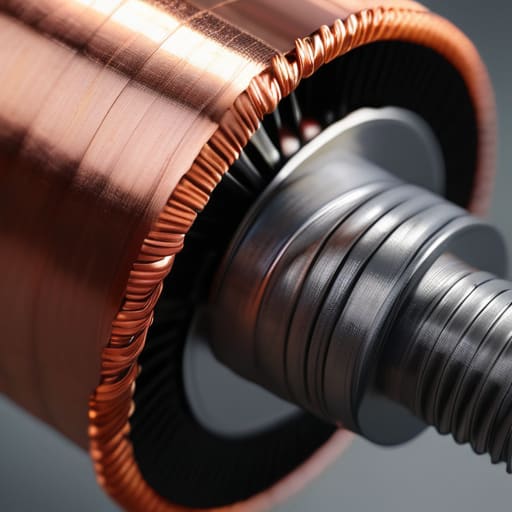
If you think you can just loop some wire around a core and call it a day, you’re going to have a bad time when you get to the testing bench. I’ve seen too many beginners treat winding tension and precision like they’re knitting a sweater. If your tension is inconsistent—meaning some loops are tight and others are loose—you aren’t just making a messy-looking coil; you’re creating varying air gaps and changing the internal geometry. This causes your inductance to drift, and suddenly that value you derived from a calculating inductance formula is nothing more than a suggestion. You need to keep that wire taut and uniform, or you’ll be chasing phantom readings all night.
Another thing people overlook is how the physical pressure of your winding affects the core itself. If you’re using ferrite, don’t go at it like you’re trying to crush a walnut. Excessive pressure can introduce micro-fractures in the magnetic core materials, which changes the permeability and ruins your Q factor. I usually wrap my coils around a mandrel and use a steady, rhythmic pull to ensure every turn sits exactly where the last one did. It’s tedious, sure, but it’s the difference between a component that performs and one that’s just a piece of scrap wire.
Five Things Your Textbook Forgot About Real-World Inductance
- Watch your parasitic capacitance like a hawk. If you wind your turns too tightly against each other, you aren’t just making an inductor; you’re making a capacitor. I’ve seen plenty of “perfect” designs fail because the turns were so close they started coupling, and suddenly your resonant frequency is nowhere near where the math said it would be. Leave a little breathing room between the turns.
- Don’t skimp on the bobbin or the form. If you’re winding directly onto a piece of scrap wood or a flimsy plastic tube that flexes when you apply tension, your inductance is going to shift every time you breathe on it. I use a solid, non-conductive form every single time because if the geometry moves, the measurement is garbage.
- Mind the lead wires. This is where most people trip up. You can wind the most beautiful coil in the world, but if you attach long, spindly wires to the ends, those leads have their own inductance and capacitance that will mess with your readings. Keep your connections short, stout, and as close to the coil as possible to minimize the “ghost” inductance.
- Be prepared for the “drift” factor. Even if you think you’ve got the tension perfect, temperature changes will affect your results. I’ve been out on a ridge in October where a ten-degree drop in temperature shifted my inductor’s value just enough to throw my filter off. If your application is sensitive, you need to test your component in the environment where it’s actually going to live, not just in a climate-controlled lab.
- Use the right wire gauge for the job, not just the one that fits easiest. If you use wire that’s too thin, your DC resistance climbs, and you’ll lose your efficiency to heat. I’ve spent too many nights troubleshooting a circuit only to realize I’d built a very expensive heater instead of a functional inductor because I wanted to save a few millimeters of copper.
The Real-World Summary
Stop treating your math as gospel; a perfect calculation on paper means nothing if you don’t account for the physical reality of wire spacing, core saturation, and the way your hands actually move while winding.
Tension is your most important tool—if you wind loose, your inductance will drift every time the temperature changes or the wind blows, turning your carefully tuned circuit into a guessing game.
Always measure what you actually built, not what you intended to build; if the meter says it’s off, don’t blame the equipment, go back and look at how those turns are actually sitting on the core.
The Gap Between Theory and Reality
You can run the math a thousand times and get a perfect theoretical value, but if you wind that coil with loose, uneven tension, your inductance is going to drift the second the temperature changes or the component settles. A good inductor isn’t just a number on a datasheet; it’s the result of how much care you put into the physical consistency of every single turn.
Wren Castellano
The Reality of the Final Turn
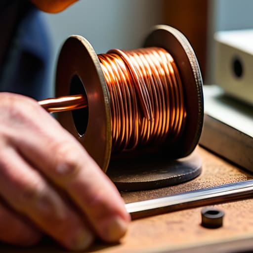
At the end of the day, winding an inductor isn’t just about following a formula or making sure the wire looks neat on the bobbin. It’s about the intersection of math and physical reality. You can calculate your target inductance to three decimal places, but if you don’t maintain consistent tension or if you let your turns wander, you’re just building a very expensive piece of scrap. Remember that consistency is your best friend here; every loose loop or uneven gap is a variable that will eventually haunt your measurements when you’re trying to tune your matching network. If your inductance drifts when the component warms up, you didn’t fail the math—you likely failed the mechanical execution.
There is a specific kind of satisfaction that comes from looking at a component you built by hand and seeing it perform exactly as intended on the analyzer. In a world of “black box” modules and overpriced pre-made parts, taking the time to understand the physics of what you’re holding is what keeps this hobby alive. Don’t be discouraged if your first few attempts are off the charts; even the best engineers have had to scrap a coil because they wound it too loosely. Just keep measuring, keep adjusting, and trust your tools more than your intuition. Once you get it right, you aren’t just using a circuit—you’re mastering it.
Frequently Asked Questions
If I'm using a core with a high permeability, how much does the spacing between the individual turns actually affect my final reading?
It affects it more than you might think. When you’re using a high-permeability core, you’re essentially concentrating a massive amount of magnetic flux into a very small space. If your spacing isn’t tight and consistent, you’re increasing the distributed capacitance between the turns. That’s going to shift your self-resonant frequency and make your inductance readings drift. Don’t trust the math blindly; if your turns are sloppy, your “calculated” value won’t match what the meter says.
Is there a point where adding more turns becomes a waste of time because the parasitic capacitance is going to tank my high-frequency performance anyway?
Absolutely. There is a massive point where you’re just building a capacitor and calling it an inductor. As you add turns, you’re increasing the proximity of those wires, which spikes your parasitic capacitance. Eventually, that capacitance starts fighting your inductance so hard that your self-resonant frequency (SRF) plummets. If you’re aiming for HF, you might get away with it, but if you’re pushing toward VHF, stop winding and start looking at your spacing.
When I'm winding these for a specific filter project, should I be worried about the temperature coefficient of the core, or is that only an issue for high-power transmitters?
If you’re building a filter, you absolutely need to care. It’s not just about high-power heat; it’s about stability. If your core’s permeability shifts even slightly as the ambient temperature changes—say, from a cool morning to a midday sun on the hill—your center frequency is going to drift. A filter that works at 14 MHz at dawn might be off-center by noon. Check the datasheet for the temperature coefficient; don’t just assume it’s constant.
