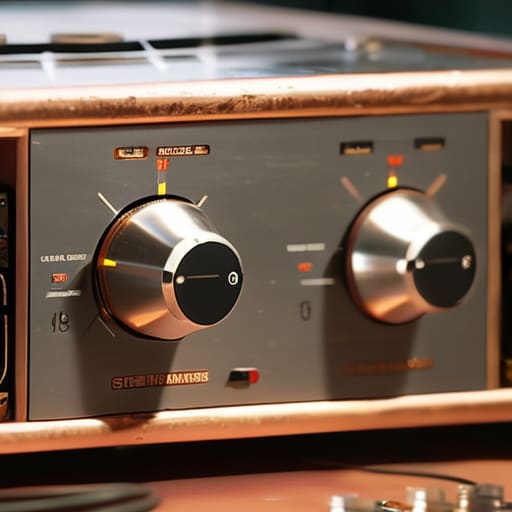
I remember sitting in my father’s garage at sixteen, staring at a drift-heavy communications receiver that felt more like a puzzle than a radio, trying to follow a service manual that felt like it was written in a different language. I spent three hours turning trimmer capacitors based on “expert” advice from a forum post that was older than I am, only to realize I was just chasing ghosts and making the selectivity worse. If you think learning how to align an old receiver is just about blindly following a series of numbered steps in a dusty PDF, you’re going to end up with a piece of gear that’s more frustrating than useful. The truth is, alignment isn’t about following a ritual; it’s about understanding the signal path and knowing when a measurement actually means something versus when you’re just fighting component aging.
In this guide, I’m stripping away the guesswork and the outdated folklore. I’ll show you how to use real test gear to verify your work, because if you aren’t measuring the intermediate frequencies, you aren’t aligning—you’re just guessing. We’re going to look at practical, repeatable methods for adjusting IF transformers and local oscillators so that your rig actually performs like the precision instrument it was meant to be.
Table of Contents
- Step-by-Step Instructions
- Vintage Audio Equipment Calibration Beyond the Manual
- Signal Strength Optimization Using Proven Tracking Techniques
- Don't Just Turn Knobs: Five Real-World Rules for Alignment
- The Reality Check: What Actually Matters When You’re Tuning
- The Reality of the Alignment Process
- The Final Check
- Frequently Asked Questions
Guide Overview
Tools & Supplies
- Signal Generator for injecting test tones
- Oscilloscope for visualizing waveforms
- Non-conductive Alignment Tool for adjusting variable capacitors
- Multimeter for checking voltage rails
- Schematic Diagram specific to the receiver model
- Contact Cleaner for cleaning potentiometers
Step-by-Step Instructions
- 1. Before you even touch a screwdriver, you need to get your signal source under control. I’ve seen too many people try to align a rig using a signal from a neighbor’s station or a local broadcast, and that’s a recipe for chasing ghosts. You need a stable, calibrated signal generator—or at least a known, steady source—and you need to feed it directly into the receiver via a shielded cable. If you’re using a signal generator, set it to a frequency well within the band you’re testing and keep the amplitude low enough that you aren’t driving the front end into compression.
- 2. Clean your contacts and check your power rails first. It sounds trivial, but I’ve spent more hours than I care to admit troubleshooting a “misaligned” receiver only to find a layer of oxidation on a decade-old potentiometer or a drifting voltage regulator. Use some high-quality contact cleaner on the band switches and volume pots, and then verify your DC voltages against the service manual. If your rails are sagging or noisy, no amount of fine-tuning the IF stages is going to give you a clean signal; you’ll just be tuning a mess.
- 3. Start with the RF stage, but don’t go overboard. Your goal here is to ensure the signal is actually making it through the front end to the mixer without getting lost in the weeds. Adjust the RF gain stages just enough to see a strong signal on your meter or scope, but stop before you hit saturation. If you push the gain too hard during this step, you’ll create intermodulation products that make the next steps nearly impossible. I always check the signal at a height of about two meters above my workbench to minimize capacitive coupling from my own body, though with a direct cable, it shouldn’t matter much.
- 4. Now we move to the Intermediate Frequency (IF) alignment, which is where the real work happens. This is the heart of the receiver’s selectivity. You’ll want to adjust the IF transformer slugs to maximize the output signal strength at your target frequency. Don’t just twist them blindly; use a non-metallic adjustment tool to avoid shifting the inductance with your screwdriver. I usually do this by watching a signal strength meter or a trace on an oscilloscope; you’re looking for that peak response where the signal is cleanest and strongest.
- 5. Once the IF is peaked, you have to align the local oscillator (LO). This is where people usually mess up by trying to do everything at once. You want to sweep the frequency and ensure that the difference between your RF input and your LO output is exactly what the IF transformers are designed for. If you find that you can’t get a peak at the high end of the band, your LO might be drifting due to an aging capacitor. Check your oscillator stability before you move on, or you’ll find yourself re-doing the entire process in twenty minutes.
- 6. Finally, perform a selectivity test to make sure your filters are actually doing their job. I like to inject a carrier on my target frequency and then quickly sweep a second signal nearby to see how sharply the receiver rejects the adjacent signal. If the “skirt” of your filter is too wide, you’re going to have a hard time pulling weak stations out of the noise when the band gets crowded. It’s better to be a little too selective than to have a receiver that turns every strong signal into a blurry mess of interference.
Vintage Audio Equipment Calibration Beyond the Manual
Look, the service manual is a great starting point, but it was written for a technician in a climate-controlled factory in 1974, not for you sitting at a workbench with a piece of gear that’s spent forty years breathing dust. When you’re performing vintage audio equipment calibration, you have to account for component drift. Capacitors age, and resistors wander. If you follow the manual’s voltage specs to the letter without looking at the actual behavior of the circuit, you’re just chasing ghosts. I’ve seen plenty of people “fix” a rig only to find the IF stages are slightly out of whack because they didn’t account for the thermal stability of the old components.
If you want real results, stop treating this like a checklist and start using audio signal tracking techniques to see how the signal actually moves through the stages. Don’t just nudge a trimmer because a book told you to; watch the output. If you’re tuning old radio receivers, pay attention to the noise floor. Sometimes, the “perfect” alignment according to the manual actually results in a narrower bandwidth than the original design intended due to component aging. You have to find the sweet spot where the signal is clean, but you aren’t sacrificing the natural warmth of the original circuitry.
Signal Strength Optimization Using Proven Tracking Techniques
Once you’ve finished the heavy lifting of the initial receiver alignment procedure, you’ll often find that the signal still feels a bit “soft” or inconsistent. This is where most people stop, thinking they’re done, but that’s exactly when you miss the chance to turn a functional rig into a high-performance one. I’ve spent enough nights on ridges to know that a signal isn’t just about the components being in place; it’s about how the stages interact. To get real signal strength optimization, you need to move beyond the basic dial settings and start looking at the intermediate frequency (IF) response across the entire tuning range.
Don’t just trust your ears; your ears will lie to you if the local noise floor is high or if you’re tired. Instead, use a calibrated signal generator to sweep through the bands. I prefer using manual audio signal tracking techniques—watching how the amplitude fluctuates as you nudge the trimmer capacitors—rather than just blindly following a schematic. If you see a dip in the middle of the band, you haven’t truly finished tuning old radio receivers; you’ve just stopped halfway. Real precision comes from finding the peak and staying there, even when the manual says a different value is “acceptable.”
Don't Just Turn Knobs: Five Real-World Rules for Alignment
- Stop chasing the peak with your eyes closed. If you’re adjusting IF transformers, use a signal generator with a stable output and a calibrated meter. If you’re just “eyeballing” the signal strength on a noisy dial, you aren’t aligning the receiver; you’re just guessing, and you’re going to end up with a narrow bandwidth that kills your selectivity.
- Check your DC rails before you touch a single trimmer. I’ve spent too many afternoons chasing a drifting oscillator only to realize a twenty-year-old electrolytic capacitor was leaking voltage and dropping the rail by half a volt. If the power isn’t steady, your alignment won’t be either.
- Temperature is your silent enemy. I don’t care if the manual says you can align it on your kitchen table; if that rig hasn’t been powered on for an hour, you’re wasting your time. Let the components reach thermal equilibrium first, or you’ll find yourself re-aligning the same stage twenty minutes later because the drift caught up to you.
- Respect the “Good Enough” threshold. You don’t need to hit the theoretical peak of every single stage to get a working radio. If you push the alignment too hard to find a mathematical maximum, you often end up with a filter response so steep that the slightest component drift makes the radio unusable. Aim for a broad, stable peak, not a razor-thin one.
- Document the “Before” and the “After.” Keep a notebook. If you adjust a trimmer and the signal jumps up, write down the value or the position. If you don’t, and you accidentally overshoot the sweet spot, you’re going to be staring at a dead band wondering which way to turn the screwdriver to get back to where you started.
The Reality Check: What Actually Matters When You’re Tuning
Stop treating the factory manual like scripture; it was written for a lab environment that doesn’t exist in your garage, so trust your meter and your ears over a 40-year-old printed instruction.
Alignment is useless if your environment is a mess—if your antenna is sitting three feet off the ground or your coax is leaking, you aren’t tuning the receiver, you’re just chasing ghosts.
Always distinguish between a hardware fix and a “good day” on the bands; if you’ve dialed in the gain and the signal still vanishes, it’s likely the ionosphere playing games, not your calibration.
The Reality of the Alignment Process
Stop treating the service manual like it’s scripture; those technicians wrote those specs for a factory floor in 1974, not for the component drift and thermal noise you’re dealing with in your garage today. You don’t align a receiver to hit a number on a page—you align it to find the sweet spot where the signal actually survives the trip from the antenna to your ears.
Wren Castellano
The Final Check
At the end of the day, aligning an old receiver isn’t about following a checklist until you’re blue in the face; it’s about understanding the relationship between the components you’re adjusting. We’ve moved past the theoretical fluff and looked at the actual mechanics—from verifying the IF stages to ensuring your signal tracking isn’t just chasing noise. Remember, if your alignment seems “off” despite following the steps, don’t just keep turning the trimmer capacitors. Check your input signal stability first. I’ve lost more hours to a jittery signal generator than I have to faulty vintage circuitry, and I’ll be damned if I don’t tell you that. If you haven’t accounted for the actual signal-to-noise ratio at your test point, you aren’t aligning; you’re just guessing.
There is a specific kind of satisfaction that comes from hearing a weak, distant signal snap into clarity because you took the time to do the math and the manual labor correctly. In a world where everything is a black box or a software-defined mystery, there is something deeply grounding about a piece of gear where you can actually see the physics in action. Don’t let the complexity intimidate you. Keep your workbench clean, keep your measurements honest, and remember that radio is a physical discipline. Once you master the hardware, the airwaves start to feel a lot less like magic and a lot more like home.
Frequently Asked Questions
If I don't have a calibrated signal generator, can I get a decent enough alignment using a known strong local station, or am I just going to ruin the IF stages?
You won’t ruin the IF stages—those are solid-state or vacuum tubes, not glass; they aren’t going to shatter just because you’re hunting a signal. But honestly? Using a local station is a gamble. You’re chasing a moving target, and if that station’s transmitter is drifting or the ionosphere decides to take a nap, your alignment will be garbage. It’s fine for a rough “sanity check,” but if you want precision, find a cheap, used signal generator.
How much does the actual input voltage at the antenna jack matter during the alignment process—should I be compensating for a low-gain antenna or just working with what I've got?
It matters immensely. If you’re trying to align a receiver using a low-gain antenna or a suboptimal feedline, you aren’t calibrating the rig; you’re just compensating for a bad signal-to-noise ratio. I never align using a real antenna. I use a signal generator and a calibrated attenuator. If you don’t know exactly how many dBm are hitting that jack, you’re just chasing ghosts. Get a stable, known source first, or you’re wasting your time.
Once I've dialed in the peak sensitivity, how do I know if I've actually improved the selectivity or if I've just accidentally widened the bandwidth and started letting in more noise?
That’s the million-dollar question. If you just crank the gain, you aren’t improving selectivity; you’re just making the noise floor louder. To know for sure, you need to test the adjacent channel rejection. Tune to your carrier, then nudge the dial just outside your target bandwidth. If the signal drops off sharply, you’ve actually tightened the filters. If the noise floor stays flat or the signal bleeds through, you’ve just widened the gate.
