
I was halfway up a ridge in the Cascades, shivering in a light drizzle and nursing a lukewarm flask of tea, when my transceiver decided to play its favorite game: silence. No signal, no carrier, just a dead screen that would suddenly spring back to life the moment I adjusted my footing. Most of the forums will tell you that you’re dealing with a complex software glitch or a failing oscillator, but let me tell you, that’s usually nonsense. When you’re out in the field, learning how to fix intermittent faults isn’t about running expensive diagnostic software; it’s about realizing that a slightly loose coax connector or a hairline crack in a solder joint is more likely the culprit than a digital ghost.
I’m not here to sell you a proprietary test jig or a way to blame the ionosphere for your poor craftsmanship. In this guide, I’m going to show you how to actually isolate a problem using the tools you already have in your kit. I’ll share the specific, measured steps I use to track down those maddening signal fades, from checking your grounding to testing for mechanical fatigue under load. We’re going to stop guessing and start measuring, because if you don’t find the physical cause, you haven’t fixed a thing.
Table of Contents
Root Cause Analysis for Intermittent Errors Not Guesswork
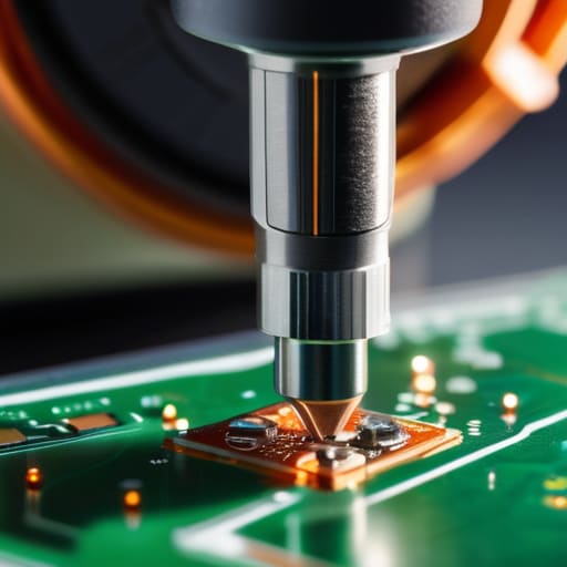
When you’re staring at a signal that drops out every time the wind picks up or the transceiver warms up, your first instinct is probably to swap out a component. Don’t. That’s how you end up with a drawer full of expensive, perfectly functional parts and a problem that’s still there. Real root cause analysis for intermittent errors starts with isolating the variable. Is it thermal expansion in a solder joint? Is it a cracked trace that only makes contact when the chassis is warm? Or is it just a mechanical failure in a connector that’s been bumped too many times?
You have to stop treating the symptom and start looking for the trigger. I’ve spent many a night on a ridge realizing that what I thought was a failing oscillator was actually just environmental factors in circuit failure—specifically, a coaxial connection that wasn’t seated properly because of the way I’d lashed the cable to my tripod. Grab a multimeter and a steady hand; if you aren’t observing how the fault reacts to physical movement or temperature changes, you aren’t troubleshooting, you’re just gambling.
Testing for Loose Connections Instead of Relying on Luck

If you’re sitting there watching a signal fade on your waterfall display and assuming it’s just a solar cycle, stop. Most of the time, you aren’t looking at a temperamental ionosphere; you’re looking at a mechanical failure. Testing for loose connections isn’t just about checking if a plug is seated; it’s about the integrity of the contact under stress. I’ve spent more nights than I care to admit chasing signal integrity issues that turned out to be nothing more than a slightly oxidized BNC connector or a solder joint that looked perfect but had a microscopic fracture hidden under the heat shrink.
Don’t just poke at the wires with your finger and hope for the best. That’s how you end up breaking a brittle trace on a PCB. Instead, use a dedicated multimeter or, if you’re feeling thorough, a specialized diagnostic tool to check for voltage drops while you physically manipulate the cable. If you move a coax lead and the SWR spikes or the audio cuts, you’ve found your culprit. It’s not magic, and it’s not luck—it’s just a bad physical link that needs a proper fix.
Five Ways to Stop Guessing and Start Finding the Fault
- Stop the “wiggle test” with your hands and start using a mechanical probe; if you’re just shaking a connector until it works, you aren’t finding the failure, you’re just masking it until the next time you walk away.
- Check your power supply rails under load, not just at idle; I’ve lost count of how many “intermittent” signal fades turned out to be a capacitor in a cheap switching supply that couldn’t handle the current draw when the rig actually started transmitting.
- Map your thermal environment because heat is a thief; if the fault only appears twenty minutes into a session, stop looking at the schematic and start looking at which component is getting hot enough to expand a micro-crack in a solder joint.
- Use a spectrum analyzer or a high-speed scope to catch the transient, not just the aftermath; if you’re only looking at the meter after the signal has already dropped, you’re reading a history book instead of watching the crime happen in real-time.
- Document the environmental variables—humidity, temperature, and even the position of your antenna—because if a fault only triggers when the wind picks up or the sun goes down, you’re likely looking at a shielding issue or a ground loop rather than a failed component.
The TL;DR for When Your Rig Acts Up
Stop the “tap and pray” method; if you aren’t using a multimeter or a signal tracer to isolate a physical break, you aren’t troubleshooting, you’re just gambling.
Environmental variables aren’t just excuses—if your SWR spikes only when the wind picks up or the sun goes down, you’ve got a mechanical or thermal issue, not a magic ghost in the machine.
Document your baseline measurements under known “good” conditions so you actually have a number to compare against when things go sideways.
The Trap of the "Good Day"
If your rig starts working perfectly just as you’re packing up to head home, don’t congratulate yourself on a successful session—congratulate yourself on finding the exact moment the thermal expansion or a slight vibration finally settled the fault. An intermittent problem isn’t “fixed” until you can replicate the failure on command; otherwise, you aren’t an engineer, you’re just a spectator watching the ionosphere play tricks on your patience.
Wren Castellano
Stop Guessing and Start Measuring

At the end of the day, fixing an intermittent fault isn’t about having a “feel” for the gear or waiting for the problem to reappear so you can stare at it. It’s about the data. We’ve talked about moving past the guesswork, moving from vague observations to actual measurements, and specifically isolating the physical connection points that are failing you. Whether it’s a cold solder joint that only opens up when the rig gets warm, or a coax connector that’s losing continuity every time the wind kicks up, you won’t find the culprit by sitting there hoping for a repeat performance. You find it by stress-testing the system—mechanically, thermally, and electrically—until the numbers tell you exactly where the break is.
I know it’s frustrating. There is nothing quite as maddening as a station that works perfectly for three hours and then goes silent just as you’re about to make a contact. But don’t let that frustration turn into apathy. Every time you successfully track down a ghost using a meter instead of a prayer, you’re becoming a better operator and a better engineer. Radio is a physical medium, and it obeys the laws of physics even when it feels like it’s playing tricks on you. Trust your measurements, keep your tools calibrated, and remember that the goal isn’t just to get back on the air—it’s to understand exactly why you’re there.
Frequently Asked Questions
How do I tell the difference between a physical connection issue and a component failing due to thermal drift once the rig gets warm?
If it’s a loose connection, the signal usually cuts out when you physically nudge the cable or the chassis. It’s mechanical. But if it’s thermal drift, it’ll be predictable: the rig works fine for twenty minutes, then the frequency drifts or the signal fades as the components reach operating temperature. Grab a can of freeze spray. Hit the suspected component; if the fault clears instantly, you aren’t looking at a bad solder joint—you’re looking at a component that’s dying.
If my SWR is jumping around but my connections all look solid, should I be looking at the coax shielding or something inside the transceiver?
If your connections look solid but the SWR is dancing, stop looking at the transceiver for a second. Most “internal” issues are actually external. Check your coax shielding first—specifically look for micro-fractures in the braid or moisture ingress. If the shield is compromised, your impedance is fluctuating wildly. I once spent three hours blaming a bad finals stage only to find a pinched dielectric in a coax run. Test the cable with a TDR if you can; don’t assume the rig is broken just because it’s easier than tracing a cable.
When I'm out in the field, what's the most reliable way to isolate a fault if I don't have a full bench setup with me?
When you’re stuck on a ridge with nothing but a pack and a radio, stop trying to be a technician and start being a detective. Your best tool isn’t a scope; it’s the “half-split” method. Break your signal chain in half. If the signal is clean at the antenna but dead at the rig, the fault is in the coax or the connector. If it’s dead at the antenna, you’ve isolated the problem to the feedline. Narrow the search area until the culprit has nowhere left to hide.
