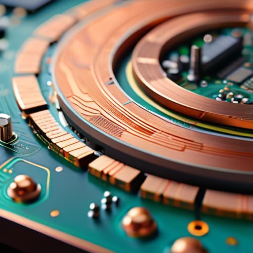
I remember sitting in my first university lab, surrounded by students who thought a Printed Circuit Board was just some magic green slab that made the magic happen. They’d stare at a finished board like it was a finished sculpture, completely ignoring the fact that it’s actually a calculated map of copper and physics. I spent years watching people overcomplicate the question of what is a pcb, treating it like some high-level mystery instead of the practical, essential tool it is. They’d buy expensive, pre-made modules when a simple, well-designed board would have done the job better and cheaper, all because they didn’t understand the traces under their fingers.
I’m not here to give you a textbook definition that you can find on a Wikipedia page. Instead, I’m going to show you how these boards actually behave when you’re pushing high-frequency signals through them. We’ll talk about traces, ground planes, and why your layout matters more than the components you’re slapping on top. My promise is simple: I’ll give you the real-world mechanics of how a PCB functions, without the academic fluff or the marketing hype.
Table of Contents
- The Truth About Copper Traces in Electronics
- Substrate Materials for Pcb More Than Just Green Plastic
- Five Things the Textbooks Skip About Designing Your First Board
- The Bottom Line Before You Start Soldering
- ## More Than a Piece of Green Board
- Beyond the Solder and the Silkscreen
- Frequently Asked Questions
The Truth About Copper Traces in Electronics

When people talk about copper traces in electronics, they often treat them like simple wires that just happen to be flat. That’s a mistake. In my experience, especially when I’m looking at high-frequency RF layouts, a trace isn’t just a path; it’s a transmission line. If you treat a trace like a piece of string, you’re going to run into impedance mismatches that will make your signal look like garbage before it even leaves the board. You have to consider the width, the thickness, and how that copper sits on the substrate.
The complexity really ramps up when you move from a basic single layer vs multi-layer pcb comparison. In a single-layer board, you’re mostly just trying to get from point A to point B without a short. But once you step into multilayer circuit board design, those traces become part of a much larger, three-dimensional puzzle. You’ve got ground planes to manage, parasitic capacitance to worry about, and layers that have to play nice with each other. It’s not just about making connections; it’s about managing the physics of the signal as it travels through the copper.
Substrate Materials for Pcb More Than Just Green Plastic
Most people see a green board and think “plastic,” but that’s a mistake. What you’re actually looking at is a sandwich of engineered materials, usually a glass-reinforced epoxy known as FR-4. It’s the industry standard for a reason: it’s cheap, it’s reliable, and it doesn’t fall apart when things get warm. However, if you’re working on high-frequency RF projects like I do, FR-4 can be a real headache because its dielectric constant isn’t as stable as you’d like. When I’m designing for higher frequencies, I often look toward specialized substrate materials for PCB like Rogers or Teflon-based boards. They handle signal loss much better, though they’ll definitely bite a hole in your budget.
The choice of material also dictates how you handle multilayer circuit board design. In a single-layer setup, you’re basically just laying copper on a sheet, but as soon as you move into multi-layer territory, the substrate has to act as a precise insulator between those internal planes. If your substrate is inconsistent, your impedance calculations go out the window, and suddenly your carefully designed traces are nothing more than antennas for noise.
Five Things the Textbooks Skip About Designing Your First Board
- Don’t trust a trace width just because a calculator told you it works; if you’re running more than a few hundred milliamps through a thin line, that trace is going to act like a heating element, and your signal integrity will go right out the window.
- Always plan for your ground plane before you even think about where the signal goes, because a PCB without a solid, continuous return path is just a very expensive way to create a glorified antenna that picks up every bit of interference in the room.
- Watch your component spacing, especially if you’re working with anything high-frequency; if you cram everything too close together, you aren’t just saving space, you’re creating parasitic capacitance that’ll make your impedance matching a total nightmare.
- Remember that a PCB is a physical object in a real environment, not a perfect mathematical model, so if you’re designing something for a portable rig, leave enough room for the heat to actually escape and for your fingers to actually reach the components when it comes time to troubleshoot.
- Test your continuity and shorts with a multimeter before you ever apply power, because I’ve seen enough “magic smoke” moments to know that a single stray bit of solder or a bridged trace can turn a week of hard work into a very expensive paperweight in less than a second.
The Bottom Line Before You Start Soldering
Don’t mistake a PCB for a magic component; it’s a structural and electrical map where the quality of your traces and the choice of substrate determine whether your signal actually makes it to the destination or just turns into heat.
The “green stuff” is just a carrier—what actually matters is the dielectric constant of your substrate and how well your copper traces are laid out to handle the specific impedance your circuit requires.
If you’re building something high-frequency, remember that a PCB isn’t just a way to hold parts in place; it’s a precision-engineered part of your RF path where every millimeter of trace counts.
## More Than a Piece of Green Board
“People look at a PCB and see a static piece of green plastic, but once you start running signals through it, you realize it’s actually a complex, high-speed plumbing system. If your traces aren’t sized right for the current or your substrate is too lossy for the frequency, you aren’t building a circuit—you’re building a very expensive heater.”
Wren Castellano
Beyond the Solder and the Silkscreen
At the end of the day, a PCB isn’t just a piece of fiberglass with some metal stuck to it; it is the physical map that tells electricity exactly where to go and how to behave. We’ve talked about how the substrate dictates your signal integrity and how those copper traces are essentially your high-speed highways. If you ignore the material properties or treat the trace width like an afterthought, you aren’t building a circuit—you’re building a headache. Whether you are designing a simple low-frequency filter for a HF rig or a high-speed digital interface, the interplay between the copper and the substrate is what determines if your project actually functions or just sits there as a very expensive paperweight.
My advice? Don’t get intimidated by the complexity, but never stop respecting the physics. It is easy to get lost in the software of modern EDA tools, clicking buttons until a layout looks “pretty,” but remember that every trace is a real-world component subject to resistance, inductance, and heat. There is a profound satisfaction in laying down a board, seeing the first signal trace through an oscilloscope, and knowing that you didn’t just follow a tutorial—you understood the medium. Get your hands dirty, measure your results, and remember that the best designs are built on fundamentals, not just fancy software.
Frequently Asked Questions
If I'm building something for my shack, does it actually matter if I use a cheap single-sided board versus a professional double-sided one?
If you’re just building a simple LED flasher, a single-sided board is fine. But for anything in your shack—especially if it’s part of your signal chain—go double-sided. Single-sided boards force you into a mess of jumper wires to get signals from point A to point B, and those wires are just little antennas for noise. A professional double-sided board lets you use ground planes, which is the only way to keep your RF floor from climbing into the weeds.
How much does the thickness of those copper traces actually impact the signal, especially when I'm dealing with higher frequencies?
At low frequencies, you can get away with thin traces, but once you start pushing into the VHF/UHF range, trace thickness becomes a real variable. It’s not just about current carrying capacity—though that matters for heat—it’s about impedance. If your trace is too thin, your impedance climbs, and suddenly you’re looking at reflections instead of a clean signal. I’ve seen too many SDR builds fail because the designer treated high-frequency traces like simple DC wires.
Can I just etch my own boards at home, or am I going to end up with a mess of short circuits and unreliable connections?
Look, you can certainly etch at home, but don’t expect a professional finish. If you’re just making a simple continuity tester or a low-frequency audio project, go for it. But if you’re trying to build a high-frequency RF front end where trace impedance actually matters, home-etching is a recipe for frustration. You’ll deal with uneven copper thickness and “under-etching” that creates parasitic capacitance. For anything precision-critical, stick to a fab.
