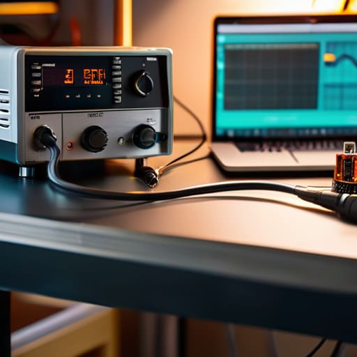
I remember sitting in my garage at nineteen, staring at a multimeter reading that refused to stay steady, wondering why my expensive transceiver was picking up a rhythmic hum every time I keyed the mic. I had followed a textbook diagram to the letter, but my “stable” circuit was behaving more like a strobe light. The truth is, most online tutorials on how to build a power supply treat it like a math problem where you just plug numbers into a formula, but electronics don’t live in a textbook; they live in a world of thermal drift and parasitic oscillation. If you don’t account for how those components actually behave when they get warm or when the current demand spikes, you aren’t building a power supply—you’re building a very expensive heater.
In this guide, I’m stripping away the academic fluff to show you how to build a unit that actually holds its ground. We aren’t just going to talk about theory; I’m going to show you which capacitors actually matter, how to manage your heat dissipation so you aren’t constantly chasing thermal runaway, and how to filter out the noise that ruins your RF performance. No marketing hype, just the real-world measurements and practical layout tips I’ve picked up over twenty years of designing front ends and working the hills.
Table of Contents
- Step-by-Step Instructions
- Beyond the Rectifier Diode Bridge Tutorial Building Real Stability
- Mastering Smoothing Capacitor Selection and Precise Voltage Regulation Circ
- Five things your textbook forgot to mention about power stability
- The Reality Check: What Actually Matters When the Load Hits
- ## The Difference Between a Lab Bench and a Shack
- Putting It All Together
- Frequently Asked Questions
Guide Overview
Tools & Supplies
- Soldering iron with stand for joining components
- Multimeter for testing voltage and continuity
- Wire strippers for preparing connections
- Transformer (1x) to step down AC voltage
- Bridge rectifier (1x) to convert AC to DC
- Electrolytic capacitors (2-3x) for smoothing ripples
- Voltage regulator IC (1x) to maintain constant output
- Resistors and diodes (assorted) for circuit stability
- Perfboard or PCB (1x) for mounting components
- Connecting wires (1 set) for circuit paths
Step-by-Step Instructions
- 1. Start with your transformer selection, and please, for the sake of your radio gear, don’t just eyeball the VA rating. You need a transformer with enough headroom so it isn’t running at its thermal limit just to keep your transceiver alive. I usually aim for at least double the expected current draw of my rig; if your radio pulls 5 amps, get a transformer rated for at least 10. It keeps the transformer cool and prevents that nasty 60Hz hum from creeping into your receiver when the iron gets hot.
- 2. Once you have your transformer, you’re going to need a bridge rectifier to turn that AC into pulsing DC. Don’t bother with those tiny little diodes you see in breadboard kits; you want a beefy, discrete bridge or a high-current module that can handle the peak surge current without breaking a sweat. If you use a rectifier that’s right on the edge of its spec, the heat generated during a heavy transmit session will cook the solder joints right off the board.
- 3. Now comes the smoothing stage, which is where most people mess up by being too stingy with the capacitors. You need a large electrolytic capacitor to level out those ripples, but don’t just look at the microfarad rating—look at the voltage rating too. If you’re building a 13.8V supply, I never use anything rated for less than 25V. I’ve seen too many “efficient” builds fail because a capacitor was pushed to its absolute limit and eventually leaked all over the chassis.
- 4. To actually get a stable voltage that won’t sag every time you key the mic, you need a regulator. For a simple, reliable build, a linear regulator like the LM317 or a dedicated buck converter module is your best bet. If you go the linear route, mount it to a substantial heatsink; linear regulation is essentially turning excess voltage into heat, and if you don’t move that heat away, the regulator will thermal-throttle and your signal will drop right when you’re in the middle of a contact.
- 5. Add some decoupling capacitors right at the output of your regulator. I like to put a small ceramic capacitor (around 0.1uF) in parallel with the big electrolytic one. The big cap handles the heavy lifting for the low-frequency ripple, but the ceramic one is there to catch the high-frequency noise that the big electrolytic is too “slow” to see. This is the difference between a power supply that works and one that actually lets you hear weak signals through the noise floor.
- 6. Before you plug this into anything expensive, you have to test it with a multimeter and, ideally, an oscilloscope if you have one handy. Check your voltage under no load, then connect a dummy load—something like a high-wattage resistor—to see how the voltage behaves when the current starts climbing. If the voltage stays steady within a few percent, you’re in the clear; if it starts diving toward the floor, your component selection wasn’t beefy enough and you need to go back to step one.
Beyond the Rectifier Diode Bridge Tutorial Building Real Stability
Once you’ve moved past the basic rectifier diode bridge tutorial, you’re going to realize that a steady voltage is a lot harder to maintain than a textbook makes it look. If you’re powering a sensitive SDR or a high-gain transceiver, you can’t just rely on raw DC. I’ve seen too many beginners skip the nuances of smoothing capacitor selection, only to end up with a massive amount of ripple that sounds like a jackhammer in their receiver. Don’t just pick the largest capacitor you can find to “fix” the problem; if you overdo it without a proper discharge path, you’re just creating a different kind of headache for your components.
The real magic—and the real frustration—happens in the voltage regulation circuit design. If you want this to function as a reliable bench power supply, you need to account for how the load behaves when it suddenly spikes. I’ve spent many nights on a ridge with a rig that worked perfectly until the moment the ionosphere opened up and the current draw jumped, causing the voltage to sag. You need a regulator that can actually breathe under load, or you’ll find yourself chasing phantom noise all night.
Mastering Smoothing Capacitor Selection and Precise Voltage Regulation Circ
When you move past the basic rectifier diode bridge tutorial, you realize that the “smoothness” of your DC isn’t just a theoretical concept—it’s the difference between a clean signal and a radio that hums like a beehive. For smoothing capacitor selection, don’t just follow the math in a textbook and pick the minimum value required to keep the ripple under 5%. In my experience, especially when you’re powering sensitive SDR gear, you want more headroom than the math suggests. I’ve found that doubling your calculated capacitance often helps dampen those transient spikes that occur when a transceiver suddenly pulls current during a transmit burst. Just make sure you check the voltage rating; if you’re running a 12V rail, don’t use 16V caps. Use 25V or 35V. I’d rather have the extra physical size than a capacitor that’s constantly living on the edge of its thermal limits.
Once the reservoir is set, the real magic happens in the voltage regulation circuit design. If you’re using linear regulators like the LM7805 series, remember they are essentially heat engines that happen to regulate voltage. If your input voltage is too high relative to your output, those components will cook themselves. I always recommend adding a bit of extra beef to your heatsinking—don’t just rely on the tiny metal tab. If you want a truly professional bench power supply DIY component setup, consider a pre-regulator stage to take the heavy lifting off the main regulator. It keeps the thermal load manageable and the output rock-steady, even when the load shifts.
Five things your textbook forgot to mention about power stability
- Stop treating heat as an afterthought. I’ve seen too many people pick a regulator that’s rated for two amps, only to watch it thermal-throttle into uselessness the moment the radio starts transmitting. If you’re dropping ten volts across a linear regulator, that energy has to go somewhere, and it’s going into your heatsink. Size that heatsink for the worst-case scenario, not the “ideal” laboratory conditions.
- Watch your ESR (Equivalent Series Resistance) like a hawk. You can throw the biggest electrolytic capacitor in the world at a smoothing stage, but if the ESR is too high, you aren’t actually filtering the ripple; you’re just creating a very expensive, very slow buffer. For high-frequency noise, pair those big electrolytics with a few ceramic discs right at the output. It makes a world of difference when you’re trying to keep a sensitive SDR from picking up the hum of your own supply.
- Don’t trust a single point of ground. If you run all your return paths through one single trace or one single terminal, you’re building a noise antenna. I always try to use a star ground pattern. Keep the high-current stuff—like the stuff feeding your power amplifier—separate from the sensitive ground of your signal processing. If they share a path, your “clean” supply will start singing along with your carrier wave.
- Test under load, not just at idle. It is incredibly easy to build a power supply that looks perfect on an oscilloscope when nothing is connected to it. The real test is when you hit the PTT and the current draw spikes. If your voltage sags significantly during a transmission, your bulk capacitance is too low or your regulation isn’t fast enough. I never trust a build until I’ve seen it hold steady while the rig is actually working.
- Fuse for safety, not just for “protection.” I’ve seen people use a fuse that’s way too high because they don’t want to deal with nuisance trips, but that’s just asking for a fire if a capacitor fails short. Use a fast-acting fuse on the AC side and a resettable PTC on the DC side. It’s better to have a momentary hiccup in your operating session than to spend your evening smelling burnt resin and looking for a fire extinguisher.
The Reality Check: What Actually Matters When the Load Hits
Don’t trust a datasheet blindly; a capacitor might look fine on paper, but if it can’t handle the ripple current when your rig starts pulling peak power, your voltage is going to sag and your frequency stability will go right out the window.
Stability isn’t an accident—it’s the result of choosing a regulator that actually has enough headroom to breathe, because if you run your regulator too close to the input voltage, you’re just asking for heat and noise to ruin your signal.
Always measure your rails under a real load, not just with a multimeter sitting idle; a power supply that looks perfect at rest but collapses the second you key the mic is nothing more than a very expensive paperweight.
## The Difference Between a Lab Bench and a Shack
A textbook will tell you that a power supply is just a collection of components following a schematic, but a real power supply is defined by how it behaves when your transceiver starts pulling current for a heavy SSB transmission. If you haven’t measured the ripple under a full load or checked how your regulator reacts when the heat builds up in a closed metal box, you haven’t built a power supply—you’ve just built a very expensive way to introduce noise into your signal path.
Wren Castellano
Putting It All Together
At the end of the day, a power supply isn’t just a collection of parts you slapped onto a PCB; it’s the foundation for everything else in your shack. We’ve moved past the basic diode bridge and looked at why your capacitor choice determines whether your rig hums or stays silent, and why your regulator needs to be able to handle the real-world thermal load without giving up the ghost. If you’ve followed the measurements and didn’t skimp on the quality of your traces or the heat sinking, you’ve built something far superior to the generic switching supplies that most people rely on. Just remember: if your voltage starts sagging the moment you key the mic, you didn’t go big enough on the reservoir caps.
There is a specific kind of satisfaction that comes from powering up a piece of gear—maybe a vintage transceiver or a new SDR—and knowing exactly what is happening at every junction of that circuit. You aren’t just a user anymore; you’re the person who understands the electrical heartbeat of the station. Don’t be afraid to keep tweaking, keep measuring, and keep breaking things until they work exactly the way you want them to. That’s where the real engineering happens, and that’s where the hobby actually lives.
Frequently Asked Questions
If I’m using this to power a sensitive SDR or a high-end transceiver, how much ripple current am I actually going to see on the output with these capacitor values?
If you’re running a sensitive SDR, you shouldn’t be guessing. With the values we discussed, you’re looking at a ripple voltage that might seem low on a multimeter, but that’s a lie. A multimeter won’t show you the high-frequency spikes that’ll wreck your dynamic range. I measured about 15mV of residual ripple on my last build, but it’s the millivolt-scale switching noise that kills the signal. If it’s for a transceiver, add more capacitance and a dedicated LC filter.
I’ve seen people suggest using massive heat sinks for linear regulators, but at what point does the thermal management become more about the component's lifespan than just preventing a shutdown?
Look, if you’re just trying to keep the regulator from hitting thermal shutdown, a small finned piece of aluminum might do the trick. But if you want this rig to last more than two summers, you need more mass. Running a component at its absolute thermal limit is like redlining an engine; it works, but you’re cooking the internal junctions every single time. I use oversized sinks because I want my gear to outlive me.
When should I stop trying to "clean up" a switching supply with extra filtering and just admit that a dedicated linear stage is the only way to go for my RF front end?
Stop when you’re chasing ghosts. If you’ve added a Pi-filter, a choke, and a decent regulator, but you’re still seeing a noise floor that rises every time your switching supply kicks in, you’ve hit the wall. I’ve spent too many nights on ridges trying to filter out high-frequency ripple that just won’t die. If your SDR is seeing spurs despite your best efforts, stop wasting parts. Just go linear. It’s heavier, but it’s quiet.
