I remember sitting on a ridge in the Cascades three years ago, staring at a transceiver that insisted everything was fine while my signal was hitting a brick wall. I was relying entirely on the built-in SWR meter, which is basically just a glorified guessing machine that tells you if you’re about to cook your finals, but nothing more. If you want to actually understand the relationship between what your rig is pushing out and what your antenna is actually accepting, you need to stop squinting at that little LED display and learn how to use a directional coupler to see the real math. It isn’t just another piece of “extra” test gear; it is the only way to see the actual flow of energy through your line.
In this guide, I’m stripping away the textbook fluff to show you how this component actually behaves in the real world. We’ll go over how to integrate one into your setup without creating a massive loss, how to read those forward and reflected readings when things get messy, and why precision matters more than a pretty reading on a screen. I’ll give you the practical steps to move past guesswork and start measuring your system like a real engineer.
Table of Contents
- Step-by-Step Instructions
- The Truth About Insertion Loss vs Coupling Factor
- Measuring Forward and Reflected Power Without the Guesswork
- Five Things I Learned the Hard Way (So You Don't Have To)
- The Bottom Line: What to Remember When You're On the Line
- ## Stop Flying Blind
- Don't Fly Blind
- Frequently Asked Questions
Guide Overview
Tools & Supplies
- Vector Network Analyzer (VNA) or Spectrum Analyzer for measuring S-parameters
- Solder station with fine tip for coaxial connections
- Multimeter for continuity and resistance checks
- Directional Coupler (the specific component for your frequency range)
- Coaxial cables (SMA or N-type, depending on coupler ports)
- RF connectors and adapters for matching components
Step-by-Step Instructions
- 1. First, you need to decide where this thing actually lives in your signal chain. If you’re using a standalone coupler, it goes between your transmitter and your antenna (or your dummy load). If you’re using a built-in one in a transceiver, you’re already set, but you need to make sure your external meter is actually capable of reading the specific coupling ratio of the device. A 20dB coupler isn’t going to give you the same resolution as a 40dB one, so don’t expect to see every tiny ripple in the line if your hardware isn’t matched to the job.
- 2. Check your connections before you even think about hitting the PTT. I’ve seen too many people blow a fuse or a meter because they had a loose coax connection that created a phantom mismatch. Tighten your connectors, ensure there’s no moisture in the lines, and if you’re using a directional coupler in a portable setup, make sure the mounting is secure. A loose connector will give you a reading that looks like a bad antenna, when really it’s just a bad junction.
- 3. Set your meter to the correct scale. This is where people trip up most often. If your coupler is rated at -20dB, that means the signal going to your meter is 1/100th of your actual output power. If you’re pumping out 100 watts and you forget to account for that math conversion, you’re going to be staring at a needle that says you’re running 1 watt, and you’ll spend three hours chasing a ghost. Always double-check the ratio printed on the side of the coupler.
- 4. Start with a low-power test. I don’t care how confident you are in your antenna deployment; never, ever key up at full rated power on a new setup. Drop your power down to a few watts and check your forward power first. Once you see that the meter is actually responding to the signal, you know your coupling path is intact. If you see forward power but the needle isn’t moving, you likely have a dead meter or a blown internal fuse in the coupler itself.
- 5. Now, look at the reflected power. This is the whole reason we bother with these things. If you see a high reading on the “Reflected” side, you have a mismatch. Don’t just assume the antenna is bad; check the impedance of your feedline and your tuning unit. If you’re using a long wire antenna at 10 meters above ground, your SWR might be fine at 40 meters but absolutely tank at 20 meters because the ground interaction changed the effective electrical length.
- 6. Compare the forward and reflected readings to calculate your actual SWR. While most modern rigs do this for you, doing the manual math with a good analog meter gives you a much better “feel” for the line. If your forward power is 50W and your reflected power is 5W, you’re in the ballpark. If that reflected number jumps to 25W, stop transmitting immediately. You’re wasting energy as heat, and you’re asking for trouble in your final transistors.
- 7. Finalize your setup by observing the readings under real-world load. If you’re operating portable, remember that moving your antenna or even just walking near the feedpoint can change these numbers. I always like to see a stable reading for at least a minute before I commit to a long contact. If the needle is dancing, something is physically moving or electrically unstable in your system, and you’ll never get a clean signal through that mess.
The Truth About Insertion Loss vs Coupling Factor
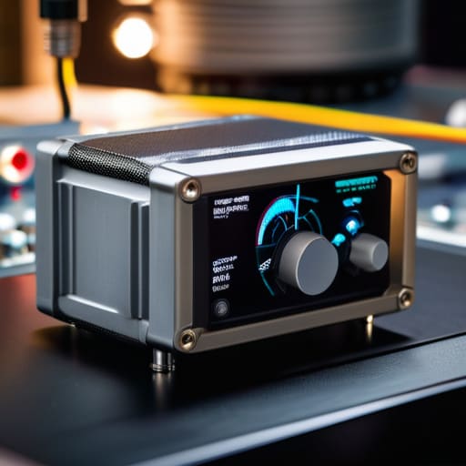
Here is the reality that most spec sheets won’t tell you: there is a massive difference between the coupling factor and the actual signal you’re seeing on your meter. When you look at a coupler, the coupling factor (like 20dB or 30dB) tells you how much the signal is being attenuated before it hits your monitoring port. But you need to keep a close eye on the insertion loss, which is the power lost simply by passing the signal through the device itself. If you’re working on a low-power QRP setup or trying to squeeze every decibel out of a weak signal on a portable rig, a cheap coupler with high insertion loss can actually degrade your performance more than you realize.
I’ve seen plenty of people get frustrated because their readings seem “off” during RF signal monitoring. Usually, they’ve forgotten that the coupler isn’t a perfect magic box. You have to account for the fact that even a high-quality component introduces a tiny bit of resistance. When I’m setting up my RF test bench configuration, I always calculate the expected loss first so I’m not chasing ghosts. If your readings are drifting, don’t just assume the ionosphere is acting up; check if your coupler is actually performing within its rated specs under load.
Measuring Forward and Reflected Power Without the Guesswork
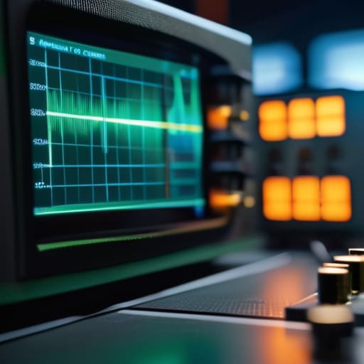
When you’re setting up your RF test bench configuration, the biggest mistake I see is people treating the coupler like a magic black box. They plug it in, see a number, and assume they’re golden. But if you aren’t looking at the relationship between those two readings, you’re flying blind. To actually master measuring forward and reflected power, you have to understand that the reflected reading isn’t just a “bad” number; it’s the most honest feedback your system can give you. If your forward power is steady but your reflected power is jittery, you likely have a mechanical issue in your connector or a cable that’s been crushed under a heavy gear bag.
I’ve spent many evenings on a ridge where a slight shift in the antenna’s height—even just a few inches—completely changed my readings. This is where directivity and isolation come into play. A high-quality coupler ensures that the signal you’re seeing on the reflected port is actually the energy bouncing back, not just leaked noise from the forward path. If your coupler has poor isolation, your readings will be garbage, and you’ll end up chasing ghosts in your tuning instead of fixing the actual mismatch.
Five Things I Learned the Hard Way (So You Don't Have To)
- Watch your power limits like a hawk. A coupler might be rated for 100 watts, but if you’re pushing a high-duty cycle mode like FT8 and that heat starts building up, you’re going to cook the internal components. I’ve seen more than one “indestructible” coupler turn into a very expensive paperweight because someone forgot that heat is the enemy of everything.
- Mind the direction of the arrows. It sounds patronizing, I know, but I’ve seen plenty of beginners—and honestly, a few old-timers too—plug things in backward. If those little arrows aren’t pointing from the transmitter toward the antenna, your readings are going to be nonsense, and you’ll spend an hour troubleshooting a perfectly good line.
- Don’t ignore the connector quality. You can have a world-class coupler, but if you’re using cheap, oxidized PL-259s to hook it up, you’re just introducing more loss and noise into the equation. If you’re measuring something as sensitive as reflected power, every milliohm of resistance in those connectors is going to mess with your data.
- Realize that a coupler isn’t a magic wand for bad antennas. If your SWR is high, the coupler is just the messenger telling you that your antenna isn’t resonant or your feedline is damaged. Don’t use the readings to justify a bad setup; use them to find exactly where the mismatch is happening so you can actually fix it.
- Account for your cable length when doing precision work. If you’re using the coupler to calibrate a system, remember that the cable between the coupler and your meter matters. I always try to keep my test leads as short and high-quality as possible; otherwise, you’re just measuring the characteristics of your patch cables instead of your actual RF path.
The Bottom Line: What to Remember When You're On the Line
Don’t mistake a low SWR reading for a perfect system; use your coupler to watch the actual power flow, because a healthy SWR doesn’t tell you if your coax is leaking or if your finals are starting to cook.
Respect the insertion loss—if you’re using a cheap, poorly made coupler, you’re just trading one set of measurement errors for another by killing your signal before it even hits the antenna.
Always account for your environment; a coupler reading might look stable on your bench, but once you get that antenna up 30 feet in the air and the wind starts blowing, those real-world reflected power numbers are the only thing that will tell you if your tuning is actually holding.
## Stop Flying Blind
A directional coupler isn’t just another box in your signal chain; it’s your eyes on the line. If you’re just staring at a needle on a meter and hoping for the best, you aren’t operating, you’re just guessing—and in this hobby, guessing is a fast way to turn an expensive transceiver into a very heavy paperweight.
Wren Castellano
Don't Fly Blind
At the end of the day, a directional coupler isn’t just another piece of kit to clutter up your workbench; it’s your eyes on the line. We’ve talked about why you can’t ignore insertion loss and why you need to know the difference between what’s going out and what’s coming back to haunt you. If you stop relying on a simple SWR meter and start looking at the actual relationship between forward and reflected power, you’ll catch issues before they become expensive lessons. Whether you’re tuning a wire antenna 30 feet up a tree or checking a feedline in a cramped shack, knowing exactly how much energy is actually reaching your antenna is the only way to move from guessing to true precision.
I know it’s tempting to just see a “low SWR” on a digital display and call it a day, but radio is a physical, messy science. The ionosphere will change, your antenna height will shift with the wind, and your coax will behave differently when the temperature drops at dusk. Don’t let the gear do all the thinking for you. Get comfortable with the numbers, learn the quirks of your specific setup, and trust your measurements more than the marketing brochures. That’s how you stop being just another operator and start being someone who actually understands the magic happening on the airwaves.
Frequently Asked Questions
If I’m using a directional coupler with an SDR, how much of that insertion loss is actually going to hurt my noise floor?
If you’re running an SDR, that insertion loss is a bigger deal than it is on a high-power rig. When you’re hunting weak signals, every 0.1 dB matters. If your coupler is adding 0.5 dB of loss, you aren’t just losing signal; you’re effectively raising your noise floor by that same margin. It’s a double whammy. If you’re doing serious DX or weak-signal work, don’t cheap out on a high-quality, low-loss component.
Can I use a coupler designed for a high-power HF rig on a low-power QRP setup, or am I just wasting precision?
You can, but you might be overpaying for precision you can’t actually use. A high-power HF coupler is built to handle heat and voltage that your QRP rig won’t even dream of producing. It’ll work fine, but you’re carrying around extra bulk and cost for headroom you don’t need. If you’re hiking a ridge for a portable setup, don’t lug a heavy high-power unit; a lightweight, low-power coupler is more than enough.
What happens to my readings if the coupler is mounted near a high-power switching power supply or other noisy gear?
If you’ve got a switching power supply sitting right next to your coupler, expect your readings to look like a mess. Those supplies are notorious for leaking high-frequency noise, and if that EMI couples into your sense lines or the coupler’s internal circuitry, your meter is going to lie to you. I’ve seen “phantom” power readings that were nothing more than induction from a nearby transformer. Keep your sensitive measurement gear away from the noisy stuff.
