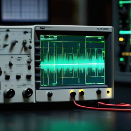
I remember sitting in a cramped lab back in the late nineties, staring at a multimeter reading that insisted my power supply was perfectly steady, while my transceiver was behaving like it had a fever. I was chasing a ghost in the circuit, relying on a little two-digit LCD to tell me the truth when the truth was actually a high-frequency oscillation that no voltmeter could ever catch. People often ask me, “what is an oscilloscope for?” and they expect a textbook definition about visualizing voltage over time. But if you’re just looking for a definition, go buy a dictionary; if you’re looking to stop flying blind during a build, you need to understand that an oscilloscope is actually your eyes for the invisible chaos happening in your wires.
I’m not here to sell you on some shiny, overpriced benchtop unit with more features than you’ll use in a lifetime. My goal is to give you the straight talk on how to use this tool to actually solve problems, from debugging a noisy SDR front-end to seeing exactly why your filter is clipping. I’ll tell you when a cheap handheld is plenty and when you’re just wasting your money on bandwidth you’ll never touch.
Table of Contents
- Mastering Electrical Waveform Analysis Beyond Simple Voltmeter Readings
- Measuring Voltage Over Time to Catch the Glitches You Miss
- Stop Guessing and Start Seeing: 5 Ways an Oscilloscope Actually Saves Your Sanity
- The Bottom Line: When to Put Down the Multimeter
- ## Stop Guessing and Start Seeing
- Stop Guessing and Start Seeing
- Frequently Asked Questions
Mastering Electrical Waveform Analysis Beyond Simple Voltmeter Readings
If you’re still relying solely on a multimeter to diagnose a circuit, you’re essentially trying to describe a movie by looking at a single, frozen photograph. A multimeter is great for telling me if a battery is dead or if a trace is broken, but it’s useless when you need to see how a signal actually behaves. When I’m troubleshooting a poorly filtered power supply for my SDR, I don’t just want to know the average voltage; I need to see the ripple. This is where electrical waveform analysis becomes the difference between “I think this is the problem” and “I know exactly where the noise is coming from.”
Real-world signals aren’t perfect sine waves living in a textbook. They are messy, they glitch, and they spike. By mastering measuring voltage over time, you start to see the transient spikes that happen when a relay clicks or a switching regulator kicks in—events that happen too fast for a digital readout to ever catch. Whether you are using an older analog unit or a modern digital one, the goal is the same: stop looking at numbers and start looking at the shape of the electricity.
Measuring Voltage Over Time to Catch the Glitches You Miss
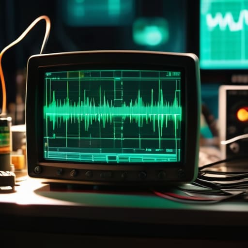
If you’ve only ever used a multimeter, you’re essentially looking at a photograph of a race and trying to tell me who won. A multimeter gives you a number—a snapshot of the average or the peak—but it tells you nothing about the chaos happening in between those readings. When I’m troubleshooting a power supply for a portable rig or checking the output of a small amplifier, I’m not just looking for 13.8 volts; I’m looking for the transient spikes that occur the moment the PTT is keyed. Measuring voltage over time is the only way to catch those millisecond-long glitches that can fry a sensitive SDR front-end before your eyes even blink.
This is where actual oscilloscope signal visualization becomes your best friend. Instead of seeing a steady line, you see the reality: the ripple from a poorly filtered DC source or the momentary sag when a high-power stage draws current. I remember once spending three hours chasing a “ghost” interference on a VHF setup, only to realize with an oscilloscope that my regulator was oscillating at a frequency I couldn’t see with a DMM. If you aren’t looking at the waveform, you’re just guessing.
Stop Guessing and Start Seeing: 5 Ways an Oscilloscope Actually Saves Your Sanity
- Stop trusting your multimeter for high-speed transients. A DMM is great for telling me my power supply is sitting at 13.8V, but it’s blind to the microsecond voltage spikes that are currently cooking your sensitive SDR front-end. If you aren’t seeing the spike on a scope, it’s probably already broken something.
- Use it to hunt down parasitic oscillations. I’ve spent more nights than I care to admit chasing a “noisy” amplifier only to find it was oscillating at a frequency my eyes couldn’t see and my ears couldn’t hear. An oscilloscope lets you see that unintended sine wave dancing on top of your carrier before you blow a transistor.
- Check your signal integrity, not just your signal strength. It’s one thing to have a signal; it’s another to have a clean one. If your square waves look more like rounded hills, your rise times are trash, and no amount of gain is going to fix the data errors you’re about to encounter.
- Validate your filter designs in the real world. You can run all the SPICE simulations you want on your laptop, but those models don’t know about the component tolerances or the stray capacitance in your breadboard. I always probe the output of a new low-pass filter to see if the actual roll-off matches what I calculated.
- Debugging your clock sources. If your microcontroller or your radio’s local oscillator is drifting or jittering, a multimeter will just show you a steady average. You need to see the actual period and the stability of that waveform to know if your timing is actually reliable or just lucky.
The Bottom Line: When to Put Down the Multimeter
If you’re looking for a steady DC voltage or a slow-moving signal, stick to your multimeter; don’t waste your time or your budget trying to “catch” a transient with a tool that isn’t built for it.
An oscilloscope is your only way to see the actual shape of a signal, which is the difference between knowing a circuit is “on” and knowing that your power supply is actually dumping high-frequency noise into your sensitive RF front end.
Use an oscilloscope to hunt for the “ghosts” in your system—those millisecond-long glitches or ringing edges that cause a microchip to reset or a radio to lose lock—because if you can’t see the waveform, you’re just chasing your tail.
## Stop Guessing and Start Seeing
A multimeter tells you the average of what happened, but an oscilloscope tells you the truth about what is actually happening; it’s the difference between reading a summary of a storm and actually standing out in the rain to see where the lightning is hitting.
Wren Castellano
Stop Guessing and Start Seeing

At the end of the day, an oscilloscope isn’t just another expensive piece of kit to clutter your workbench; it is the difference between knowing your circuit is working and actually knowing why it isn’t. We’ve talked about moving past the limitations of a multimeter, catching those transient voltage spikes that wreak havoc on your RF front end, and finally being able to visualize the actual shape of your signal. If you are still trying to troubleshoot a noisy power supply or a drifting oscillator using nothing but a DMM and a prayer, you are essentially flying blind. You need to see the waveform in real-time to understand the relationship between time, voltage, and frequency, rather than just staring at a static number that might be lying to you.
I remember my first decent scope—it was a hand-me-down analog unit that felt like it belonged in a museum—but the moment I saw a square wave actually behaving like a square wave, everything changed. It turns the “magic” of electronics into something tangible and measurable. Don’t let the intimidating interface or the price tags scare you off; every bit of data you pull from a screen is a step toward mastering your craft. Whether you’re building a simple filter or a complex SDR interface, stop relying on luck and the ionosphere’s mood. Get the data, see the truth, and build something that actually works when you flip the switch.
Frequently Asked Questions
I’ve got a decent multimeter, so when am I actually going to hit the point where a voltmeter just isn't enough?
You’ll hit that wall the second you stop measuring steady DC and start chasing something that moves. A multimeter is great for telling me a battery is dead or a trace is continuous, but it’s essentially a blind man feeling a wall. It gives you an average, but it won’t tell you if that average is hiding a 50ns spike that’s frying your transceiver’s front end. If it happens faster than a human blink, your meter is useless.
Do I really need a high-bandwidth scope for basic antenna tuning, or am I just paying for features I'll never touch?
Look, if you’re just checking for DC offsets or looking at a slow-moving signal on a low-frequency transceiver, a cheap, entry-level scope is fine. But don’t get caught out. If you’re trying to debug a high-speed digital controller or look at actual RF transients, a low-bandwidth scope will just lie to you by smoothing everything out. Buy enough bandwidth to see the actual shape of your signal, not just a rounded-off ghost of it.
If I'm working with high-frequency RF signals, how do I stop the scope itself from becoming part of the circuit and messing up my measurements?
You’ve hit on the classic trap. Once you move into RF, your probe isn’t just a sensor; it’s a component. If you use a long, floppy ground lead, you’ve basically just built a tiny loop antenna that’s going to soak up every bit of EMI in the room and dump it right into your signal. Stop using those long alligator clips. Use a short ground spring or a coaxial probe instead. If you don’t minimize that inductance, you aren’t measuring your circuit—you’re measuring your probe.
