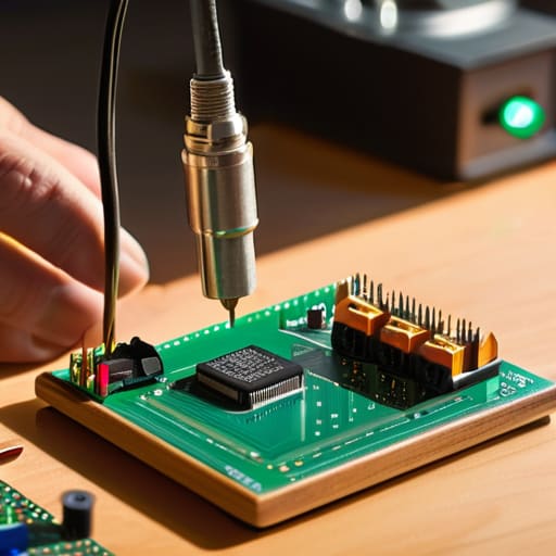
I remember sitting at my kitchen table at nineteen, staring at a pile of PCBs and a bag of components that looked more like a handful of gravel than a high-performance receiver. I’d spent three hours following the manual to the letter, only to end up with a rig that produced nothing but a low-frequency hum and a very expensive paperweight. Most people will tell you that success is just about following the instructions, but they’re wrong; if you want to learn how to build a kit that actually performs when the sun goes down, you have to understand the physics of the solder joint and the reality of component tolerances.
In this guide, I’m stripping away the textbook fluff and the “just trust the manual” nonsense. I’m going to walk you through the practicalities of component selection, why your workstation setup matters more than you think, and how to troubleshoot when your signal-to-noise ratio looks like a flat line. You won’t get any marketing hype here—just the measured, hands-on reality of turning a box of parts into a piece of gear you can actually rely on when you’re out on a hill.
Table of Contents
- Step-by-Step Instructions
- Beyond the Manual Reading Component Datasheets Like a Pro
- Precision Assembly Mastering Circuit Board Assembly and Soldering
- The Small Stuff That Makes or Breaks Your First Build
- The Real-World Bottom Line
- The Difference Between a Kit and a Radio
- The Moment of Truth
- Frequently Asked Questions
Guide Overview
Tools & Supplies
- Permanent marker for labeling components
- Scissors or utility knife for opening packaging
- Storage container (1 unit)
- Compartmentalized organizer (1 unit)
- Small items/components (various quantities)
- Label stickers (1 pack)
Step-by-Step Instructions
- 1. First, clear a space on your workbench that isn’t cluttered with half-finished projects or old coffee mugs. You need enough room to spread out the kit components without them rolling off the edge, but more importantly, you need a clean, well-lit surface. If you’re working in a dim corner, you’re going to miss a tiny solder bridge between two pins, and that’s how you end up with a short circuit that smells like magic smoke instead of radio waves.
- 2. Lay out your components and compare them to the parts list in the manual. I know, it feels tedious, but do not skip this. I once spent four hours troubleshooting a receiver only to realize the kit had shipped with a 10k resistor where a 1k should have been. Check the values, check the polarity on those electrolytic capacitors, and make sure everything is actually in the box before you pick up the iron.
- 3. Get your soldering station dialed in. If you’re using one of those cheap, temperature-controlled irons that claims to hit 400 degrees but actually fluctuates like a rogue signal, do yourself a favor and upgrade. You want a steady, predictable heat. If you overheat the pads, you’ll lift the copper trace right off the PCB, and once that happens, you aren’t just building a kit anymore—you’re performing surgery.
- 4. Start with the lowest-profile components first, usually the resistors and diodes. It’s much easier to work your way up from the board than it is to try and squeeze a bulky capacitor into a crowded layout after everything else is already in place. When you’re soldering, remember that you aren’t just melting metal; you’re creating a mechanical and electrical bond. If the joint looks like a dull, grainy ball, it’s a cold solder joint, and it will fail the moment the rig gets warm.
- 5. Once the small stuff is down, move on to the transistors, ICs, and larger capacitors. Be incredibly careful with the integrated circuits. I always recommend using a socket rather than soldering the chip directly to the board. If you mess up a pin or the chip is a dud, you can just swap it out without having to desolder the entire assembly and risk damaging the traces.
- 6. Before you even think about plugging this into a power supply, grab your multimeter. You need to perform a continuity check on your power rails to ensure there isn’t a path from positive to ground. I’ve seen too many beginners skip this step, only to hear a sickening pop the second they flip the switch. It’s much easier to fix a shorted trace now than it is to replace a fried regulator later.
- 7. Finally, if the continuity checks pass, apply power—but keep your hand on the switch. Watch the current draw on your meter. If the amperage spikes immediately, shut it down. If it settles into a steady, expected range, you’ve likely succeeded. From here, it’s just a matter of testing the signal, and if things don’t work, don’t panic; it’s usually just a matter of tracing the signal path until you find the culprit.
Beyond the Manual Reading Component Datasheets Like a Pro

When you open that instruction packet, don’t treat it like a holy text. The manual tells you where the parts go, but it rarely tells you how they behave when the temperature climbs or the power supply fluctuates. This is where reading component datasheets becomes your best defense against a pile of useless silicon. I spent three years in commercial RF before I realized that a “standard” capacitor rating is often just a suggestion. If your kit calls for a component, look up the actual curves. Check the ESR (Equivalent Series Resistance) and the thermal stability. If the datasheet shows a massive spike in leakage at 50°C, and you’re planning to run this rig in a hot car or a cramped shack, you’re going to have a bad time.
Don’t just glance at the part number and move on. I’ve seen too many beginners skip the fine print, only to realize halfway through circuit board assembly that they’ve bought a component with a voltage rating that’s way too close to their operating rails. You want some headroom. If the manual says 12V, I’m looking for something rated for at least 25V or 50V. It’s about building a margin for error, because in the real world, things rarely stay perfectly linear.
Precision Assembly Mastering Circuit Board Assembly and Soldering
Look, you can have the most expensive components in the world, but if your soldering is sloppy, you’re just building a very expensive paperweight. When you start the actual circuit board assembly, stop thinking about it as “melting metal” and start thinking about heat transfer. I’ve spent too many nights troubleshooting electronic projects only to find a single, microscopic crack in a joint that was killing my signal-to-noise ratio. If you aren’t using a decent temperature-controlled station, you’re fighting a losing battle.
The biggest mistake I see—and I’ve made it myself back when I was starting out—is rushing the process. You need to master specific soldering iron techniques, like heating the pad and the lead simultaneously rather than just dumping a blob of solder on top. If the joint looks like a dull, grey ball instead of a shiny, concave mountain, you’re preventing cold solder joints from being a thing. A cold joint might pass a continuity test, but the moment your rig warms up or you’re out in the field with a bit of wind, that connection is going to fail you. Take your time.
The Small Stuff That Makes or Breaks Your First Build
- Stop treating the component list like a grocery run. If the kit comes with generic electrolytic capacitors and you have the budget, swap them for something with a higher temperature rating. I’ve seen too many “successful” builds fail six months later because a cheap cap decided to leak right when the ambient temperature in the shack rose by five degrees.
- Check your polarity before you touch the iron. It sounds elementary, but I’ve seen more than one enthusiast turn a perfectly good diode into a tiny, expensive heater because they didn’t double-check the stripe against the silkscreen. Take ten seconds to verify the orientation of every single polarized component; those ten seconds save you a frantic trip to the component distributor.
- Don’t go overboard with the solder. You aren’t welding a bridge; you’re making an electrical connection. If you see a massive, shiny blob that looks like a teardrop, you’ve got too much. It creates parasitic capacitance that can mess with your signal integrity, especially if you’re building something high-frequency. Aim for a smooth, concave fillet that looks like a tiny mountain, not a lake.
- Clean your boards properly. Flux residue isn’t just “aesthetic”—it’s conductive. If you’re building a high-impedance circuit or something sensitive, that leftover sticky mess can create leakage paths that cause your measurements to drift. Use some high-grade Isopropyl alcohol and a stiff brush to get it spotless before you even think about applying power.
- Test as you go, not just at the end. If the kit has sub-assemblies, test them individually. If you wait until the entire thing is populated to find out that a transistor was dead on arrival, you’re going to spend three hours desoldering components just to find the culprit. It’s much easier to troubleshoot a single module than a completed, complex circuit.
The Real-World Bottom Line
Don’t treat the manual like gospel; it’s a starting point, not a guarantee. If the datasheet says a component works at a certain temperature but you’re planning to run this rig in a humid shack or a hot field bag, trust your own measurements over the marketing fluff.
Soldering isn’t just about making things stick; it’s about signal integrity. A cold joint might pass a continuity test, but it’ll introduce parasitic resistance that’ll kill your performance the moment you try to pull a signal out of a noisy band.
Always leave room for error and testing. If you build the whole thing and realize you’ve used the wrong value capacitor, you’re going to have a much harder time digging it out than if you had tested the sub-sections as you went.
The Difference Between a Kit and a Radio
A kit is just a pile of parts and a piece of fiberglass until you put something of yourself into it; if you treat the assembly like a chore instead of a measurement, you’ll end up with a box that looks right on the bench but falls apart the moment you try to pull a signal out of the noise.
Wren Castellano
The Moment of Truth
At this point, you’ve done the heavy lifting. You didn’t just blindly follow a printed manual like a robot; you actually looked at the datasheets, verified your component tolerances, and sweated over your solder joints to ensure everything was clean and secure. Remember, a kit is only as good as the attention you paid to the details that aren’t highlighted in the glossy pictures. If your measurements are off or your soldering is messy, the rig will tell you the second you apply power. But if you’ve followed this approach—treating the assembly as a measured engineering task rather than a way to kill an afternoon—you’ve built something that isn’t just a toy, but a reliable piece of hardware.
Now comes the part that makes the whole thing worth it: the first time you hear a signal break through the noise. There is a specific kind of magic in knowing that the electrons are flowing through a circuit that you assembled, piece by piece, with your own hands. It’s easy to buy a pre-built rig and press a button, but you won’t feel that same connection to the spectrum. Don’t get discouraged if your first test results aren’t perfect or if you have to tweak a few things; that’s just part of the process. Get it on the air, listen to what it’s telling you, and enjoy the fact that you actually understand how it works.
Frequently Asked Questions
I’ve followed the assembly steps, but how do I know if my solder joints are actually solid or if I've just created a high-resistance nightmare that'll drift the frequency?
If you’re worried about frequency drift, you’re right to be. A cold joint isn’t just a connection failure; it’s a variable resistor that changes as the kit warms up. Grab a magnifying lamp—don’t rely on squinting—and look for a dull, grainy surface instead of that smooth, bright sheen. If it looks like sandpaper, it’s a nightmare. Better yet, use a multimeter to check continuity, but remember: a reading doesn’t guarantee stability under load.
If I can't find the exact component specified in the kit, what's the real-world tolerance I can get away with before the circuit starts acting up?
Look, the manual says 1% tolerance, but that’s often a safety margin for manufacturing. If you’re swapping a resistor in a low-frequency part of the circuit, 5% is fine. But if you’re messing with the oscillator or a filter stage, don’t get greedy. A 10% drift there will shift your resonant frequency and turn your hard work into a very expensive paperweight. Check the datasheet; if it’s temperature-sensitive, stick to the spec.
Once the board is built and powered up, what's the proper way to use a multimeter or an oscilloscope to verify it's actually doing what the manual claims?
Don’t just power it up and pray it works. Start with the multimeter to check your rails; if your voltage is sagging 0.5V below spec, you’ve got a power supply issue or a short you missed. If you’ve got an oscilloscope, look at the signal paths. I don’t care what the manual says about “ideal waveforms”—I want to see the actual rise time and any ringing on the clock lines. If it looks messy, it’ll behave messy.
