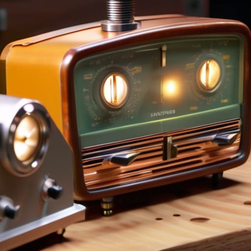
I was sitting in my workshop last Tuesday, staring at a vintage transceiver that had been nothing but a paperweight for three years, when I realized most people approach a dead rig with a “parts-swapping” mentality. They see a failed component and immediately reach for a soldering iron to replace it, blindly following a forum thread from 1987 that probably wasn’t even right to begin with. But if you want to actually learn how to repair old equipment without turning a simple fix into a permanent disaster, you have to stop guessing. You don’t need a magic touch; you need to actually measure the voltage across that capacitor before you decide it’s the culprit.
In this guide, I’m stripping away the guesswork and the expensive, unnecessary “pro-tips” that don’t hold up under a multimeter. I’ll show you how to trace a signal through a weathered circuit board, how to identify heat-stressed components that look fine but are electrically dead, and why your testing environment matters as much as the gear itself. This isn’t about memorizing schematics; it’s about developing the measured intuition required to bring a piece of history back to life.
Table of Contents
- Step-by-Step Instructions
- Essential Electronics Restoration Tools That Actually Deliver Results
- Troubleshooting Circuit Boards Without Relying on 1987s Best Guesses
- Five Hard Lessons from My Workbench
- Three Things to Remember Before You Pick Up the Soldering Iron
- The Difference Between Guessing and Knowing
- Don't Just Guess, Measure
- Frequently Asked Questions
Guide Overview
Tools & Supplies
- Multimeter for testing electrical continuity and voltage
- Screwdriver set with various bit sizes for disassembly
- Soldering iron for repairing broken connections or wires
- Cleaning kit including isopropyl alcohol and cotton swabs
- Contact cleaner spray for removing oxidation
- Replacement fuses or capacitors as needed
- Electrical tape or heat shrink tubing for insulation
- Lubricating oil for moving mechanical parts
Step-by-Step Instructions
- 1. Open the chassis and don’t just stare at it. I know it’s tempting to start poking around with a soldering iron the second you see a dusty circuit board, but you need to establish a baseline first. Use a high-resolution camera to take photos of every single connection, screw, and component orientation before you move a single thing. I’ve seen too many people “fix” a rig only to realize three days later they have four leftover screws and no idea where the shielding gasket goes.
- 2. Grab your multimeter and start with the power supply rails. Most “dead” gear isn’t actually dead; it just isn’t getting the juice it needs. Measure the voltage at the output of the transformer and check the continuity of the fuses. If you find a blown fuse, don’t just slap a new one in and hope for the best—that’s how you turn a simple repair into a fire hazard. A blown fuse is a symptom, not the disease, so look for the short circuit that killed it in the first place.
- 3. Get a magnifying glass or a decent microscope and inspect the solder joints. This is where twenty years of thermal cycling and vibration from heavy power cables comes into play. Look for “cold” joints—those dull, grainy-looking connections that don’t reflect light like a fresh solder bead should. If you see a ring around a component lead, that’s a hairline fracture. Reflowing those joints with a bit of fresh leaded solder often does more for an old transceiver than replacing an entire module.
- 4. Hunt down the electrolytic capacitors. If you’re looking at gear from the 80s or 90s, these are your primary suspects. They have a shelf life, and once the electrolyte dries up or leaks, your ripple voltage goes through the roof and your signal purity goes out the window. Don’t trust the labels; if a cap looks even slightly bulged at the top, or if there’s any crusty residue at the base, replace it immediately. I always replace the entire filter bank in a power supply regardless of how they look, because I’d rather spend twenty bucks on parts than ten hours chasing noise.
- 5. Clean the physical interfaces. I’m talking about the potentiometers and switch contacts. If your tuning knob feels crunchy or your band selector makes the signal drop out when you touch it, you’ve got oxidation. Use a high-quality contact cleaner—not the cheap stuff that leaves a greasy film—and work the controls back and forth. If a switch is particularly stubborn, you might need to take it apart, but usually, a measured application of DeoxIT is enough to bring it back to life.
- 6. Perform a functional stress test once you think you’ve won. This is where most people skip ahead to the fun part, but it’s the most important. Plug the rig into a dummy load—not your actual antenna, unless you want to risk blowing your finals because of a mistake you made during the repair—and monitor the current draw and temperature. If the heat sink is getting hotter than usual, or if the SWR on the dummy load is jumping around, you haven’t actually fixed the problem; you’ve just masked it.
Essential Electronics Restoration Tools That Actually Deliver Results
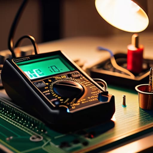
Look, you don’t need a laboratory full of $5,000 bench gear to get started, but you do need tools that don’t lie to you. If you’re diving into troubleshooting circuit boards on a rig from the late seventies, a cheap, uncalibrated multimeter is just going to give you a false sense of security. I’ve spent enough nights chasing phantom voltage drops to know that a decent, auto-ranging DMM is your best friend. Pair that with a high-quality temperature-controlled soldering station—and I mean actually controlled, not those $20 sticks that fluctuate like a solar cycle—and you’ve already avoided half the common mistakes.
When it comes to electronics restoration tools, don’t overlook the importance of a good ESR meter. If you’re following a capacitor replacement guide, measuring the Equivalent Series Resistance is the difference between a successful fix and a device that hums or fails three weeks later. Also, please, for the love of everything holy, invest in a decent variable isolation transformer. Following proper electrical safety protocols isn’t just about protecting yourself; it’s about ensuring you don’t accidentally dump a surge into a rare component that hasn’t been manufactured since the Reagan administration.
Troubleshooting Circuit Boards Without Relying on 1987s Best Guesses
When you’re staring at a PCB from a transceiver that’s been sitting in a damp garage since the Reagan administration, the temptation is to start swapping components like you’re playing a game of blindfolded Tetris. Don’t do that. Most people approach troubleshooting circuit boards by following a “if X, then Y” logic they read on a forum thread from twenty years ago. That’s a fast way to turn a repairable rig into a very expensive paperweight. Instead, I start with the power rails. I don’t care what the schematic says the voltage should be; I want to know what it is right now. If your DC voltage is sagging or oscillating, you aren’t looking for a failed transistor; you’re looking for a dried-out electrolytic that’s lost its ESR stability.
Before you even touch a soldering iron, you need to establish a baseline. I always run a visual inspection under a decent microscope first—not just to look for burns, but to look for the subtle signs of trace corrosion that the naked eye misses. Once you’ve confirmed the board isn’t physically compromised, move to signal tracing. If you can’t follow the signal path with an oscilloscope, you’re just guessing. Stop relying on “common failure points” and start following the actual physics of the circuit. If the signal disappears at a specific stage, that’s your target. Everything else is just noise.
Five Hard Lessons from My Workbench
- Stop treating electrolytic capacitors like they’re eternal. If you’re opening up a rig from the late 80s or earlier, those cans are likely dried out or leaking, even if they haven’t visibly bulged. Don’t wait for a catastrophic failure or a loud pop; replace them proactively, but check the voltage ratings first—don’t just swap a 25V cap for another 25V cap if the rail is running hot.
- Learn to respect the thermal footprint. When you’re replacing a component, don’t just shove it into the same spot if the original was heat-sinked or tucked away for a reason. I’ve seen too many people “fix” a radio only to have a new transistor fry two weeks later because they ignored the original thermal management.
- Get comfortable with the “smell test” and visual inspection before you even touch a soldering iron. Sometimes a burnt-out resistor tells a story—it’ll tell you exactly which component downstream failed and caused the overcurrent. If you just replace the resistor without finding the short that killed it, you’re just setting yourself up for a repeat performance.
- Don’t trust the service manual blindly. Those diagrams were printed when tolerances were different and components were more forgiving. If the manual says a trace should have 50 ohms and your meter is reading 200, trust your meter, not the faded ink on the page. The board in front of you is the only truth that matters.
- Document the “as-is” state before you start changing things. I’ve seen plenty of beginners (and some seasoned guys, if we’re being honest) strip a chassis down to the bare PCB and then realize they have no idea where that specific jumper wire or shielding clip went. Take photos of the wiring paths—especially the high-frequency sections—before you disturb them.
Three Things to Remember Before You Pick Up the Soldering Iron
Stop chasing ghosts from old forum posts; if the manual says the voltage should be 12.6V and your multimeter is reading 9V, trust the meter, not a thirty-year-old troubleshooting tip.
Respect the component’s history, but don’t be sentimental—if an electrolytic capacitor looks even slightly bloated or has been sitting in a hot chassis for two decades, pull it out and replace it before it leaks and eats your traces.
Always verify your work in context; a circuit might look perfect on the bench, but you haven’t truly fixed anything until you’ve tested it under load and confirmed it actually performs when the real-world conditions hit.
The Difference Between Guessing and Knowing
Stop treating a circuit board like a magic box where you just swap components until the lights come on; if you aren’t measuring the voltage rails and checking the ESR on those old electrolytic caps before you start replacing things, you aren’t repairing the rig, you’re just gambling with it.
Wren Castellano
Don't Just Guess, Measure
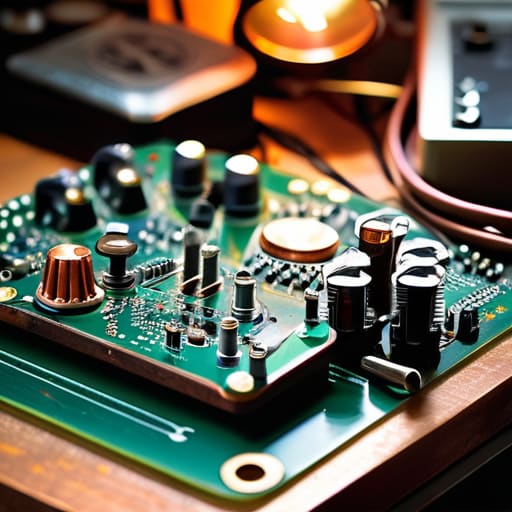
At the end of the day, repairing these old rigs isn’t about having a magic touch or a library of dusty service manuals; it’s about having the discipline to actually look at what’s happening on the bench. We’ve covered why you need to stop swapping components blindly, why your multimeter is more important than any forum thread, and why measuring the actual signal path beats following a schematic from forty years ago every single time. If you take away nothing else, remember that a capacitor doesn’t care about your intuition, and a trace doesn’t care about your hopes. Measure the voltage, check the resistance, and trust your instruments over your gut feeling. If the numbers don’t line up, the circuit isn’t fixed, no matter how much you want it to be.
There is something deeply satisfying about bringing a piece of gear back to life—hearing that first clear signal after months of silence is a feeling you just can’t get from buying a new, plastic SDR. We keep this gear running because it’s more than just silicon and copper; it’s a connection to how things used to be built, back when you could actually understand every single part of the machine. Don’t let the fear of a blown transistor keep you from the bench. Even if you only get it working because the ionosphere decided to cooperate that evening, you’ve still learned something. Keep your soldering iron hot, your eyes on the scope, and never stop asking the hardware why it’s behaving the way it is.
Frequently Asked Questions
How do I know when a component is actually failing versus just being old and "drifting" slightly out of spec?
Look, “drift” is the polite word people use when they don’t want to admit a component is dying. If a capacitor is just drifting, you’ll see a slow, predictable change in performance. But if you’re seeing erratic noise floors or sudden shifts in bias voltages, that’s not aging—that’s a failure in progress. Don’t guess. Measure the ESR on those caps and check the leakage on your diodes. If the numbers are jumping, stop calling it drift and start replacing.
If I find a leaky electrolytic capacitor, should I just replace the whole batch or only the ones that look suspicious?
If you see one leaking, the rest of that batch is already compromised. Electrolytics have a shelf life, and if they’re sitting in a rig that’s twenty or thirty years old, the electrolyte is likely drying out across the board—even if they look clean. Don’t play whack-a-mole with components; you’ll just end up back at the bench in three months when a “healthy” one fails. Replace the whole set. It’s cheaper than a blown transformer.
At what point does the cost of sourcing period-correct parts outweigh the actual value of the rig?
Look, I’ve spent more than I should on New Old Stock capacitors just to keep a specific vintage receiver sounding “right,” but there’s a line. If you’re hunting for a specific brand of electrolytic just to satisfy a purist’s checklist, you’re chasing ghosts. If the rig is a rare museum piece, hunt the parts. If it’s just your daily driver, use modern, high-spec components. Reliability and measured performance beat “period-correct” every single time.
