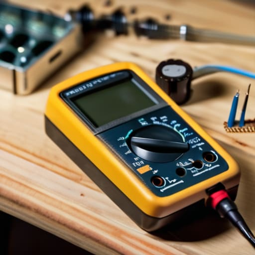
I was sitting on a ridge in the Ozarks three years ago, staring at a dead portable rig that should have been humming on 20 meters, wondering why my carefully tuned front end had gone silent. I had spent an hour swapping capacitors and checking traces, only to realize a single, tiny component had drifted into a state of partial failure—it wasn’t dead, but it wasn’t behaving, and it was wrecking my signal-to-noise ratio. Most people think learning how to test a transistor is just about checking if it’s shorted or open with a cheap meter, but if you want to actually troubleshoot a circuit that’s acting temperamental, you need to look deeper than a simple continuity beep.
In this guide, I’m going to skip the textbook definitions and show you how I actually verify these components in the field. We aren’t just going to see if a part is “good” or “bad”; I’ll show you how to check the junctions to ensure they meet the real-world parameters you need for a stable design. Whether you’re working on a vintage tube-driven rig or a modern SDR, you’ll learn how to use your gear to find the truth, even when the component is trying to hide its flaws.
Table of Contents
- Step-by-Step Instructions
- Mastering Multimeter Transistor Test Settings and Diode Mode
- Cracking the Code With a Transistor Pinout Diagram
- Real-World Lessons: What the Manuals Leave Out
- The Reality Check: What to Remember When You're at the Bench
- Beyond the Datasheet
- Beyond the Multimeter
- Frequently Asked Questions
Guide Overview
Tools & Supplies
- Digital Multimeter (Essential for measuring continuity and diode test)
- Datasheet (To identify Emitter, Base, and Collector pins)
- Assorted Transistors (Various NPN and PNP types)
- Replacement Transistors (Optional, for comparison testing)
Step-by-Step Instructions
- 1. First, clear your workbench and grab a decent digital multimeter. If you’re using one of those cheap, battery-draining units from a bargain bin, just be aware that the readings might drift as the battery dies, so check your leads first. Set your dial to the diode test mode; we aren’t looking for a perfect mathematical curve here, we’re just looking to see if the semiconductor junctions are actually behaving like junctions.
- 2. Identify your pins. You can’t test what you can’t name, and if you’re working with a modern SOT-23 surface mount component, you’re going to need a magnifying glass and a steady hand. Look up the datasheet for your specific part number to find the Base, Collector, and Emitter. Don’t guess—guessing is how you blow a fuse or, worse, fry a perfectly good driver stage.
- 3. Start with the Base-Emitter junction. Place your red (positive) probe on the Base and your black (negative) probe on the Emitter. You should see a reading between 0.5 and 0.7 volts for silicon, or maybe a bit lower if it’s germanium. If the meter reads “OL” or shows a dead short (0.00), that transistor is nothing more than a paperweight and belongs in the bin.
- 4. Now, flip the probes for the Base-Collector junction. Put the red probe on the Base and the black probe on the Collector. You should see a similar voltage drop to what you got with the Emitter. If these two readings are wildly different—say, one shows 0.6V and the other shows 0.2V—then you’ve likely got a leaky junction that will cause all sorts of headaches in your amplifier circuit.
- 5. Test the “off” state. This is where most people get lazy, but it’s vital. Reverse the probes: put the black probe on the Base and test against both the Emitter and the Collector. In both directions, the meter should show “OL” (Open Loop). If you see any significant voltage drop here, the transistor is shorted internally, and no amount of tweaking your bias voltage is going to fix it.
- 6. If you’re working with a Bipolar Junction Transistor (BJT) and want to be absolutely certain, try the hFE setting if your meter has it. This measures the DC current gain. It’s not a perfect way to see if a transistor is “good” for a specific high-frequency RF application, but it’ll tell you if the component is functionally alive before you commit it to a permanent solder joint.
Mastering Multimeter Transistor Test Settings and Diode Mode
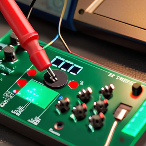
When you’re staring at a handful of components on your bench, the first mistake most people make is treating the multimeter like a magic wand. You can’t just dial it in and hope for the best. Most modern meters have a dedicated diode test mode transistor function, which is your best friend here. It provides just enough voltage to bias the junction without blowing the component. If you’re working with an older analog meter or a cheap digital one that lacks a specific transistor setting, you’ll have to rely on the diode mode to check the base-emitter and base-collector junctions individually.
Keep in mind that your approach changes depending on whether you’re dealing with n-channel vs p-channel testing in MOSFETs or standard BJTs. If you don’t have a clear transistor pinout diagram in front of you, stop. Don’t guess. I’ve seen plenty of beginners fry a perfectly good circuit because they assumed the leg order based on a visual hunch. Get the datasheet, verify your pins, and then apply the meter. It’s the difference between a quick fix and a permanent mistake.
Cracking the Code With a Transistor Pinout Diagram

Now, here is where most people trip up and start guessing. You can have the best multimeter in the world, but if you’re probing the wrong legs, you’re just chasing ghosts. I’ve spent enough late nights on the bench to know that a transistor pinout diagram isn’t just a suggestion; it’s your map. If you’re working with a through-hole component, the datasheet is your best friend, but if you’ve pulled a tiny SOT-23 surface-mount part out of a discarded radio, you’re going to need a magnifying glass and a lot of patience. Don’t assume the order is E-B-C just because it worked on a different part last week.
Once you’ve identified the pins, you need to be mindful of the specific architecture you’re dealing with. There is a massive difference in how you approach n-channel vs p-channel testing, especially when you move from standard BJTs into MOSFET territory. If you treat a field-effect transistor like a standard bipolar junction, your readings will look like nonsense, and you’ll likely conclude the part is blown when it’s actually perfectly fine. Verify the type before you even touch the probes to the leads. It saves a lot of unnecessary frustration and a lot of wasted components.
Real-World Lessons: What the Manuals Leave Out
- Don’t trust a single reading. If you’re testing a BJT, check the junctions in both directions—collector to base, then base to emitter. If it reads like a dead short in one direction but shows a healthy diode drop in the other, you’re likely okay, but if it’s shorting both ways, it’s time for the bin.
- Watch out for “ghost” readings in high-impedance circuits. If you’re testing a transistor that’s still soldered into a board, the surrounding resistors and capacitors will lie to your multimeter. Always desolder at least one leg—preferably the base—if you want a measurement that actually means something.
- Temperature matters more than you think. I’ve seen plenty of transistors pass a bench test at room temperature only to fail the moment they start drawing current in a field rig. If you’re working with power transistors, give them a little warmth or check them when they’re cold; if the readings drift wildly, the component is compromised.
- The “Diode Mode” trap. Most modern digital multimeters are great, but their internal voltage drop might not be enough to fully “wake up” certain high-threshold transistors. If you get a reading of ‘OL’ (Open Loop) on everything, don’t immediately assume it’s blown; try switching to the resistance (Ohms) scale to see if you can get a more meaningful measurement.
- Remember that a “good” reading isn’t a guarantee of performance. A transistor can pass a basic continuity or diode test and still be completely useless for RF work because its gain (hFE) has drifted outside of its spec. Testing for functionality is one thing; testing for precision is another entirely.
The Reality Check: What to Remember When You're at the Bench
Stop guessing and start measuring; a component might look perfect on the board, but if your multimeter isn’t showing the expected diode-mode drops across the junctions, it’s junk.
Never rely on a generic diagram alone; always verify your specific part number against the datasheet, because assuming the pinout is E-B-C every single time is a quick way to fry a perfectly good rig.
Understand that a “pass” on a multimeter doesn’t always mean the transistor is healthy for high-frequency work; it just means it isn’t completely dead, so keep your expectations grounded when you’re testing parts intended for sensitive RF stages.
Beyond the Datasheet
A datasheet tells you how a transistor is supposed to behave in a perfect, temperature-controlled vacuum, but your multimeter tells you how it’s behaving right now in your hand. Don’t just look for a ‘pass’ or ‘fail’—look for the leakage and the wonky junctions, because a component that’s technically ‘working’ can still be the reason your signal-to-noise ratio is absolute garbage.
Wren Castellano
Beyond the Multimeter

At the end of the day, testing a transistor isn’t about memorizing a single number from a datasheet; it’s about understanding the relationship between the base, collector, and emitter. You’ve learned to use diode mode to check for junctions, you’ve hunted down the pinout, and you’ve verified that the component isn’t just a piece of charred silicon. Just remember that a “good” reading on a cheap multimeter doesn’t always mean the part will behave perfectly under a full load in a high-frequency circuit. Always keep in mind that physical context matters—a transistor might test fine on your workbench but fail the moment it hits the heat of a real amplifier stage.
There is a certain kind of quiet satisfaction that comes from opening up a piece of gear, finding a fault, and actually knowing why it failed. In an era where most people just swap out entire boards when something goes wrong, taking the time to probe the individual components keeps the craft alive. Don’t let the complexity intimidate you; every master engineer started by staring at a handful of tiny parts and wondering what they did. Keep measuring, keep testing, and don’t be afraid to trust your own data over a manual. That is how you move from just following instructions to actually understanding the physics of what you’re building.
Frequently Asked Questions
What do I do if my multimeter shows a reading, but the transistor still fails when I actually solder it into the circuit?
If the multimeter says it’s fine but the circuit is still dead, you’re likely dealing with a “leaky” component. A multimeter test is a static snapshot; it doesn’t simulate the heat or the actual voltage swings of a working circuit. The transistor might pass a low-voltage diode test but fail when it’s under load or hitting its breakdown voltage. Honestly? Don’t waste your afternoon troubleshooting a ghost. If it’s acting temperamental, just swap it out.
If I'm testing a MOSFET instead of a standard BJT, do I need to change my approach to the diode mode test?
Yes, you absolutely do, and don’t expect it to behave like a BJT. When you switch to diode mode for a MOSFET, you aren’t looking for the base-emitter junction; you’re looking for that internal body diode. If you’re testing the Gate, be careful—the gate oxide is incredibly delicate, and a cheap multimeter can actually blow it. Test the Drain-to-Source path first. If it shows a dead short, it’s toast.
Is there a way to tell if a transistor is just "leaky" or partially damaged rather than being completely dead?
That’s the real headache, isn’t it? A dead transistor is easy—it’s just a paperweight. But a leaky one? That’s a ghost in the machine. You’ll see it when your diode tests show a tiny bit of current where there should be none, or if your gain is wandering like a lost hiker. If the junctions aren’t perfectly isolated, you’ve got a leak. It’ll pass a basic continuity test but fail the moment you put it under load.
