I spent three hours last Tuesday sitting in the dark with a spectrum analyzer, watching a spike of RFI dance across my waterfall display like it was mocking me. I had already swapped the power supply and checked my grounding, yet that broadband noise persisted, driving me toward a very un-engineer-like urge to throw my transceiver out the window. Most people will tell you to just buy a handful of snap-on beads and hope for the best, but if you don’t understand the physics of impedance, you’re just throwing money at the wall. Learning how to use ferrites to fix interference isn’t about bulk; it’s about precise placement and matching the material to the frequency that’s actually killing your signal.
In this guide, I’m skipping the textbook definitions you can find on Wikipedia and getting straight to what I’ve learned from years of measuring real-world failures. I’ll show you how to identify which ferrite material actually matters for your specific noise floor, where to choke the common-mode current without creating a mess, and how to tell if your setup is just fundamentally flawed from the start. No hype, no expensive magic tricks—just practical, measured steps to help you finally hear the stations instead of your neighbor’s LED lightbulbs.
Table of Contents
- Step-by-Step Instructions
- Measuring Ferrite Bead Effectiveness Beyond the Marketing Hype
- Signal Integrity Troubleshooting Where Placement Actually Matters
- Five Ways to Stop Playing Guesswork with Your Ferrites
- The Bottom Line: Don't Just Buy Ferrites, Use Them
- ## The Ferrite Fallacy
- The Reality Check
- Frequently Asked Questions
Guide Overview
Tools & Supplies
- Wire cutters or side cutters to trim excess cable
- Hands for positioning and securing loops
- Ferrite cores (clip-on or snap-on type) 3-5 units
- Electrical tape or Velcro ties to secure placement
Step-by-Step Instructions
- 1. Before you start buying every type of snap-on bead you see on Amazon, you need to isolate the source. Turn off every single thing in your house—fridge, LED dimmers, cheap switching power supplies, the works—and see if your noise floor drops. If the noise is still there when the house is “dead,” you aren’t dealing with RFI from your appliances; you’re likely picking up local broadcast or something much more fundamental about your antenna placement.
- 2. Get your hands on a decent set of mix types, because a “one size fits all” approach is a recipe for wasted money. You want Type 31 or 43 ferrites for general VHF/UHF work, but if you’re trying to choke out low-frequency switching noise from a computer power brick, you’ll need something with higher permeability. Don’t just grab the cheapest ones in the bulk bag; match the material to the frequency you’re actually struggling with.
- 3. Start with the “choke” method on your coax. Don’t just slap a single bead on the cable and call it a day. Instead, try creating a current loop by wrapping the coax through the ferrite several times. This increases the impedance significantly without needing a massive, expensive core. I’ve found that three turns through a medium-sized toroid often does more for a noisy HF setup than ten beads scattered randomly along a single run.
- 4. Move to the “point of entry.” This is where most people fail. You need to place a ferrite bead as close to the radio’s antenna jack as physically possible. The goal is to stop the coax from acting like a long, unintended antenna that’s sucking up noise from the room and feeding it straight into your receiver’s front end. If the noise is coming through the power line, do the same thing on the DC input cable.
- 5. Test your progress with a real measurement, not just your “feeling” that it sounds better. If you have an SDR or a rig with a decent SWR/noise floor readout, watch the numbers. If you add a bead and the noise floor doesn’t move, move the bead. Sometimes the interference isn’t traveling through the wire, but is being radiated right next to it. If that’s the case, no amount of choking the cable will save you; you’ll need to move the cable or shield the source.
- 6. Don’t forget the “common mode” problem. If you’re seeing high SWR or noise that changes wildly when you touch the microphone, your coax is likely carrying common-mode current on its outer shield. This is where a 1:1 current balun or a heavy-duty ferrite choke at the feedpoint becomes mandatory. I’ve seen plenty of guys struggle with “bad antennas” for years, only to realize their coax was just acting as the other half of the antenna system.
Measuring Ferrite Bead Effectiveness Beyond the Marketing Hype
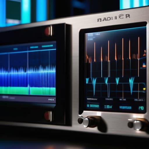
Don’t just slap a bead on a cable and assume the job is done. I’ve seen too many people walk away from a setup thinking they’ve solved their RFI problem when they’ve actually just moved the noise floor around. To truly gauge ferrite bead effectiveness, you need to stop looking at the hardware and start looking at your waterfall display. If you aren’t watching the noise floor drop in real-time on your SDR or rig, you’re just guessing. I always do a baseline sweep first—get a clean reading of the noise floor without any beads attached—and then add them one by one. If that line on the waterfall doesn’t visibly settle, you aren’t dealing with common-mode current on your coax; you’re likely dealing with something else entirely.
Sometimes, even the best high frequency noise reduction won’t save you if your placement is off. A bead placed six inches away from a connector behaves entirely differently than one placed right at the chassis ground. If you’re seeing persistent spikes, try looping the cable through the ferrite multiple times. Increasing the number of turns increases the inductive reactance, which can be the difference between a marginal fix and a clean signal. Just remember: if the noise stays high despite your best efforts, it might not be an EMI issue—it might just be a bad ground or a poorly shielded power supply.
Signal Integrity Troubleshooting Where Placement Actually Matters
If you just start slapping beads on every random wire in your shack, you aren’t troubleshooting; you’re just playing whack-a-mole. Real signal integrity troubleshooting starts with identifying the path of least resistance for that noise. I’ve spent too many nights staring at a waterfall display only to realize the RFI wasn’t coming from my power supply, but from a cheap switching regulator in a nearby LED driver. If the noise is riding on your DC lines, your ferrite needs to be as close to the radio’s power input as physically possible. If you put it halfway down the line, you’ve essentially built a tiny, useless antenna that just radiates the noise you were trying to kill.
Don’t forget that placement is everything when it comes to electromagnetic interference suppression. For RF on your coax, I always recommend a “double-tap” approach: one bead right at the antenna feed point and another right where the cable enters the shack. This creates a much more effective barrier against common-mode current. If you’re still seeing spikes on the waterfall after that, you aren’t looking at a cable issue; you’re likely dealing with a fundamental impedance mismatch or a ground loop that no amount of magnetic material is going to fix.
Five Ways to Stop Playing Guesswork with Your Ferrites
- Stop treating ferrites like magic beads; they are frequency-dependent components, not universal shields. If you’re chasing noise in the HF bands, a tiny snap-on bead designed for a USB cable is going to do absolutely nothing. Check the impedance curve on the datasheet—if it doesn’t peak where your interference is, you’re just wasting time and money.
- The “one and done” approach is a trap. If a single ferrite doesn’t kill the noise, don’t just add ten more randomly. Try a different core material or, more importantly, change the geometry. Sometimes wrapping the coax through a larger toroid three times provides more inductive reactance than a dozen cheap snap-ons ever could.
- Placement is everything, and “near the device” is often too vague. For RFI coming from a power supply, the ferrite needs to be as close to the entry point of your rig as possible. If you put it halfway down the cable, you’re just giving the noise a longer runway to hitch a ride on your shield.
- Don’t forget the common-mode current is often traveling on the outside of your shield, not the inside of the wire. If you’re seeing high SWR or strange noise floor spikes when you key the mic, your ferrite needs to be choking the common mode right where the coax meets the antenna feedpoint.
- Always verify with a real measurement, not just your gut feeling. Use your SDR or a spectrum analyzer to look at the noise floor before and after you install the bead. If the floor doesn’t drop by at least a few dB, the ferrite isn’t the fix—you likely have a fundamental grounding issue or a shield that’s been compromised by a bad crimp.
The Bottom Line: Don't Just Buy Ferrites, Use Them
Stop treating ferrites like magic dust; they aren’t a cure-all for a fundamentally broken ground system or a poorly shielded power supply.
Placement is everything—if you aren’t testing the bead as close to the entry point of the device as possible, you’re likely just choking your signal instead of cleaning it.
Always verify with a real measurement or a clear drop in the noise floor; if you can’t hear the difference on the waterfall, the ferrite isn’t doing its job and you’re just wasting money.
## The Ferrite Fallacy
Don’t just go on a shopping spree for every snap-on bead you see on the shelf; a ferrite isn’t a magic wand that cleans up a bad design. If you’re slapping them on every inch of coax without actually measuring the noise floor before and after, you aren’t troubleshooting—you’re just guessing with expensive plastic.
Wren Castellano
The Reality Check

At the end of the day, ferrites aren’t a magic wand that fixes a fundamentally broken station design, but they are a vital tool in your kit. We’ve looked at why slapping them on blindly is a waste of time and why you need to actually measure the noise floor before and after you move that bead. Remember: placement is everything. If you aren’t testing the specific point where the interference enters your signal path—whether it’s right at the transceiver’s power input or near the antenna feedline—you’re just throwing money at a problem and hoping for the best. It’s about being methodical, not lucky.
Don’t get discouraged if your first three attempts don’t drop the noise floor by 20dB. RF is a stubborn, physical beast, and sometimes the “fix” isn’t a ferrite at all, but a complete rethink of your ground plane or your cable shielding. But that’s the best part of this hobby, isn’t it? It’s the process of stripping away the mystery until you actually understand the physics of what’s happening in your shack. Keep your measurements honest, keep your cables tidy, and don’t stop testing until the signal finally sings. That’s when you know you’ve actually mastered the gear, rather than just operating it.
Frequently Asked Questions
If I slap a bunch of ferrites on my coax and the noise floor still doesn't budge, am I looking at a common-mode issue or is my power supply just fundamentally noisy?
If the ferrites aren’t moving the needle, stop twisting your hair and start isolating. If your noise floor stays flat regardless of where you choke the coax, you’re likely dealing with a noisy power supply or RFI leaking directly into your rig’s chassis. Run your radio off a dedicated battery for an hour. If the noise vanishes, your PSU is the culprit. If it stays, you’ve got a common-mode issue that your current ferrite placement isn’t catching.
Does it actually matter if I use a snap-on bead versus winding the coax through a toroid, or is that just something people say to sound technical?
It matters, and it’s not just semantics. A snap-on bead is a quick fix for high-frequency common-mode noise, but it’s limited by how much material is actually in that little plastic housing. If you want real suppression, winding the coax through a toroid is king. Every pass through the core increases your impedance. I’ve seen snap-ons do nothing for a noisy switching power supply that a well-wound FT240-43 toroid killed instantly.
Can overdoing the ferrites actually mess with my signal or impedance, or am I just chasing ghosts?
You aren’t chasing ghosts, but you can definitely overdo it. If you start slapping massive cores on your actual feedline right at the antenna connection, you’re going to mess with your impedance and potentially see your SWR climb. Ferrites are for suppressing common-mode current on the outside of the shield, not for changing the fundamental characteristics of your transmission line. Use them to clean up the noise, not to choke your signal.
