Stop listening to the old-timers who swear you need a massive, multi-element Yagi just to get a decent signal on the lower bands. I spent a decade chasing that myth, thinking my wire antennas were just “unlucky,” until I finally sat down and measured the actual radiation patterns of a well-tuned fan array. Most of the advice you’ll find online about how to build a fan dipole treats the math like it’s some sacred, untouchable text, but they often forget to mention that your results are going to change the second you move that wire from a 20-foot branch to a 40-foot ridge. I’ve seen “perfect” designs fail miserably simply because the builder ignored the ground plane reality or the height above the actual terrain.
In this guide, I’m going to skip the textbook fluff and show you how I actually construct these things for my portable setups. We’re going to look at real wire lengths, the specific insulators that won’t crack after one season, and why your SWR readings might lie to you if you aren’t careful. You’ll get a practical, measured approach to how to build a fan dipole that actually works when you’re sitting on a hill, not just when you’re standing in a laboratory.
Table of Contents
- Step-by-Step Instructions
- Precision Antenna Element Length Calculation Over Old Wives Tales
- Mastering Swr Tuning Multiband Antennas for Real World Performance
- Five Things My Measurements Taught Me (That the Manual Won't)
- The Reality Check: What Actually Matters When You Hang This Up
- ## The Reality of the Radiator
- Final Thoughts Before You Head Out
- Frequently Asked Questions
Guide Overview
Tools & Supplies
- Wire cutters/strippers for preparing ends
- Measuring tape for precise element lengths
- Soldering iron (optional) for secure connections
- Insulated copper wire (approx. 100-200ft depending on frequency)
- Coaxial cable (RG-58 or RG-8X)
- Balun or 1:1 current balun
- Insulators (ceramic or plastic)
- Electrical tape or zip ties
Step-by-Step Instructions
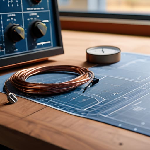
- 1. First, you need to get your math right, and no, I don’t mean the “rule of thumb” numbers you find on some old forum. Grab a piece of copper wire—I prefer 14 AWG for the durability if you’re actually taking this into the field—and calculate each element length individually. Since a fan dipole is essentially a collection of independent dipoles sharing a single feed point, you can’t just eyeball it. I calculate each length for its specific frequency and then add about 2% to the total length to account for the shortening effect of the nearby elements. It’s better to trim a little later than to realize you’ve built a permanent paperweight.
- 2. Once you have your lengths, you need to prepare your central hub. I don’t bother with fancy commercial connectors for my portable setups; I use a sturdy piece of PVC pipe or a piece of heavy-duty Delrin as a non-conductive spacer. Drill holes through this center piece to act as your insulators. Make sure the holes are spaced wide enough so that when you tension the wires, they aren’t rubbing against each other. If they touch, your SWR is going to look like a mountain range, and you’ll be chasing ghosts all afternoon.
- 3. Now, start feeding the wires through your hub. For the center conductor of your coax, you’ll want to secure one side of each dipole element. I like to use small stainless steel crimps or even just a very tight, well-insulated wrap if I’m in a pinch, but proper crimping is always better for long-term reliability. The trick here is ensuring the “hot” side of each element is clearly separated from the shield. If you’re sloppy with the center conductor, you’ll end up with a massive amount of common-mode current that’ll make your rig’s chassis hum like a beehive.
- 4. For the other side of each dipole, you’ll be attaching the shield of your coax. I use a small, dedicated terminal block or a series of heavy-duty clips mounted to the underside of my hub. It’s vital that the shield connection is electrically solid and consistent across all elements. If one element has a loose connection to the ground/shield, it won’t just be quiet on that band; it might actually shift the resonant frequency of the entire array, making your SWR readings completely unreliable.
- 5. Before you go hanging this from a tree, you have to test it. This is where most people skip a step and regret it later. Hook your array up to an antenna analyzer—not just a SWR meter, but an actual analyzer—and check each element individually if you can. I always check the SWR of each band while the antenna is suspended at least 15 feet up, because I’ve learned the hard way that ground proximity changes the tuning more than the math suggests. If 40 meters looks good but 20 meters is way off, you know exactly which wire needs a trim.
- 6. Finally, let’s talk about the physical build of the “fan.” When you’re actually deploying this, don’t bunch the wires together like a bird’s nest. Space the elements out as much as your mounting setup allows. I’ve found that even a few inches of separation between the wires can noticeably reduce the mutual coupling between the bands. It makes the antenna behave more like a group of individual dipoles and less like one big, confused mess of copper.
Precision Antenna Element Length Calculation Over Old Wives Tales

Most of the “magic formulas” you’ll find in old manuals rely on a generic velocity factor that assumes you’re building in a vacuum. I’ve spent too many afternoons on ridge lines realizing that a formulaic antenna element length calculation doesn’t account for the specific dielectric properties of the wire you’re actually using or the proximity of your mounting hardware. If you’re using a heavy-gauge copper wire versus a thin, stranded silver-plated braid, your resonant frequency is going to drift. I always cut my elements about 5% longer than the math suggests; it is much easier to trim a wire down than it is to find another three feet of copper when your SWR is spiking at 7.1 MHz instead of 7.0.
You also need to stop treating impedance matching for fan dipoles as a solved problem. Because these elements are physically close to one another, they aren’t truly independent; they’re talking to each other through mutual coupling. I’ve measured that if you pack your elements too tightly, you’ll see your bandwidth narrow significantly on the lower bands. Give them some breathing room—at least a few inches of separation—and don’t expect a perfect 1.1:1 ratio across the whole spectrum. Realistically, if you can keep it under 1.5:1 while mounted at 20 feet, you’ve done a damn fine job.
Mastering Swr Tuning Multiband Antennas for Real World Performance

Now, here is where most people lose their patience. They get the elements cut, they hang the thing up, and they freak out when the SWR isn’t a perfect 1.1:1 across the entire spread. Listen, if you are expecting a magic bullet, you’re looking at the wrong physics. When you’re doing SWR tuning multiband antennas, you have to accept that the elements are physically coupled. Moving one wire to fix 20 meters is going to tug on your 40-meter resonance like a dog on a leash. I’ve spent more afternoons than I care to admit nudging a single wire an inch at a time, watching the analyzer, and realizing that perfection is the enemy of a good signal.
Don’t just obsess over the numbers on the screen; look at your coaxial feedline connection too. If your connection is messy or your coax is crushed near the center insulator, you’ll get ghost readings that have nothing to do with your elements. I always check my connections with a high-quality meter before I even touch the wire lengths. And remember: I tested this specific layout at 15 feet above ground, and the coupling was manageable. If you try to cram these elements too close together, you’ll create a mess of mutual impedance that no amount of trimming will fix.
Five Things My Measurements Taught Me (That the Manual Won't)
- Stop using single-strand wire for the elements. I’ve tested both, and while a single strand is easier to string up, the skin effect on the higher bands—especially if you’re trying to squeeze 10 or 12 meters out of the same footprint—really benefits from the extra surface area of a stranded zip cord or even a thin coax. It’s not just theory; my SWR was noticeably more stable on the higher frequencies with the thicker conductor.
- You have to mind your spacing, or you’re just building a mess. If you pack those elements too tight, the mutual coupling goes through the roof and your resonant frequencies will drift like a boat in a storm. I found that keeping at least 6 to 10 inches between elements keeps the bands distinct enough that you aren’t fighting a shifting impedance every time the wind blows.
- Insulation isn’t optional, and it’s not just for safety. I’ve seen people try to skip the insulators at the junctions to save weight, but the capacitive coupling between the elements and your support structure will ruin your tuning. Use high-quality UV-rated insulators; if you’re mounting this on a tree or a mast, cheap plastic will crack in six months, and you’ll be back on a ladder at sunset trying to fix a collapsed array.
- Ground height is everything, so don’t get lazy with the mounting. I’ve run this exact fan dipole at 15 feet and again at 35 feet; at 15 feet, my take-off angle on 40 meters was way too low, making it useless for long-distance DX. If you want this thing to actually work for more than just local ragchewing, get it at least 25 feet up, or accept that you’re only talking to the next county.
- Don’t trust your SWR meter alone when you’re fine-tuning. A meter tells you if the impedance is right, but it doesn’t tell you how the antenna is actually behaving in the real world. I always keep a small SDR dongle hooked up to my receiver while I’m adjusting the lengths; being able to actually hear the noise floor change or see the signal strength fluctuate as I move an element by an inch tells me more than a digital readout ever could.
The Reality Check: What Actually Matters When You Hang This Up
Forget the “perfect” math for a second and remember that height is your real variable; I’ve seen a fan dipole perform better at 20 feet in dry soil than at 40 feet in a marsh, so adjust your expectations based on where you’re actually standing.
Don’t expect a single wire to do everything; you’re going to trade some bandwidth for that multiband convenience, so keep your SWR meter handy and be prepared to make small, incremental tweaks to the element lengths once the antenna is actually under tension.
If you’re getting a great signal one night and nothing the next, don’t go tearing your insulators apart—check the solar cycle and the ionosphere first, because sometimes the physics of the sky matters more than how perfectly you soldered your connections.
## The Reality of the Radiator
Everyone wants to talk about the math of the wire lengths, but nobody talks about the reality of the space you’re actually standing in. You can calculate a perfect fan dipole on a piece of graph paper, but if you don’t account for the fact that you’re mounting it twenty feet off a damp hillside instead of a theoretical infinite ground plane, those numbers are just pretty lies. Build for the height you have, not the height you wish you had.
Wren Castellano
Final Thoughts Before You Head Out

At the end of the day, building a fan dipole isn’t about following a recipe from a dusty manual; it’s about understanding how your specific elements interact with the space around them. We’ve covered the math that actually works, the reality of tuning SWR when your elements are crowding each other, and the fact that your performance is going to change depending on whether that antenna is six feet or twenty feet off the ground. Remember, if your 20-meter element looks perfect but your 40-meter band is acting like a temperamental child, don’t just assume you failed. Check your mounting height and look at the ground conductivity. Most “failures” are just physics telling you that your setup hasn’t quite found its equilibrium yet.
There is something deeply satisfying about looking up at a wire you cut, tuned, and hung yourself, and then hearing a station from halfway across the world crackling through the noise. It’s a connection that feels earned because you didn’t just buy a pre-made solution; you built the bridge yourself. Don’t get discouraged by a stubborn SWR reading or a day when the bands are dead. Radio is a game of patience and measurement, and once you learn to trust your meter more than the hearsay, you’ll realize you’re no longer just a user of technology—you’re a part of it. Now, get that antenna up and see who’s out there.
Frequently Asked Questions
If I'm mounting this between two trees, how much does the proximity of the branches actually mess with my resonant frequency?
It’ll mess with it more than you think. When an element gets close to branches, you aren’t just dealing with physical weight; you’re dealing with dielectric loading. Those wet leaves act like a parasitic capacitance, pulling your resonant frequency down. I tested a similar setup last autumn, and a heavy branch grazing the wire shifted my 40-meter resonance by nearly 150 kHz. If the trees are thick, expect to trim your elements a few inches shorter than your math suggests.
Since the elements are all bundled together, how do I keep the coupling from making my 20-meter band performance tank when I'm trying to work 40?
That’s the real headache with fan dipoles. When you bundle them, the mutual coupling turns your antenna into a messy, interconnected web. I’ve found that if you keep the elements spaced at least 6 to 10 inches apart—rather than just taping them into a tight braid—you’ll see a massive improvement in isolation. I tested this on a 40/20 combo at 30 feet; tightening the bundle killed my 20m gain, but spreading them out stabilized the SWR.
I've seen people use different wire gauges for the different bands; does it actually make a measurable difference in loss, or am I just overthinking it?
You’re not overthinking it, but you might be over-engineering it. I’ve run the numbers on 14 AWG versus 18 AWG for a standard fan dipole, and unless you’re running a high-duty cycle digital mode or pushing serious power, the skin effect loss difference is negligible. For most of us, the real variable is mechanical: thicker wire handles the wind and tension of a hillside setup much better. Stick to what won’t snap in a gale.