Blog

  • How to Set Up Remote Access to Your Own Station

    How to Set Up Remote Access to Your Own Station

    I was halfway up a ridge in the Cascades, shivering in a light drizzle, when my control link dropped for the third time in an hour. I had spent six months meticulously planning my hardware list, but I’d completely ignored the reality of signal attenuation through wet pine needles and the sheer instability of a cheap Wi-Fi bridge. Most people think learning how to set up a remote shack is just a matter of buying the most expensive SDR and a long Ethernet cable, but they’re wrong. If you don’t account for the actual environmental physics of your site—the ground conductivity, the line-of-sight obstructions, and the power stability—you aren’t building a station; you’re just building an expensive way to frustrate yourself.

    In this guide, I’m going to skip the marketing fluff and tell you what actually works when you’re miles away from a wall outlet. We’ll talk about selecting reliable low-power wide-area networks, the necessity of ruggedized enclosures, and why your choice of antenna height will dictate your success more than the rig itself. I’ll share the specific measurements I use to ensure my links stay up when the weather turns, so you can spend more time chasing DX and less time hiking back to a dead site.

    Table of Contents

    Guide Overview

    Total Time: 1-2 days
    Estimated Cost: $300-800
    Difficulty: Intermediate

    Tools & Supplies

    • Drill/Driver for securing mounting hardware
    • Multimeter for testing electrical connections
    • Wire strippers for preparing power cables
    • Weatherproof enclosure 1 unit
    • Solar panel kit 1 unit
    • Deep cycle battery 1 unit
    • Ethernet or Coaxial cabling 50-100ft
    • Mounting brackets 4 units

    Step-by-Step Instructions

    • 1. Pick your site based on RF reality, not convenience. I’ve seen too many people set up a remote shack in a valley because it was easy to hike into, only to find they’ve built themselves a Faraday cage. You need a clear view of the horizon. If you’re going for HF, you need height—and I don’t just mean the antenna. I mean the elevation of the site itself. If your site is sitting in a depression, you’re going to struggle to make anything but local contacts, no matter how much power you throw at the problem.
    • 2. Sort out your power supply before you even pack a single coaxial cable. If you’re running off a battery bank, don’t just trust a generic “capacity” rating on a label. I always calculate my actual current draw under load, including the losses from my voltage regulators. If you’re using solar, size your panels for the worst day of the year, not the brightest day in July. There is nothing more frustrating than a remote setup that goes dark right when the band opens because you didn’t account for a little cloud cover.
    • 3. Secure your link with a connection that won’t fail when the temperature drops. If you’re using a wireless bridge or a cellular modem to talk to your shack, make sure it’s hardened against the elements. I’ve spent more than one evening troubleshooting a connection that died simply because a cheap plastic housing cracked in the frost. If you can run a physical wire, do it. If you can’t, ensure your wireless link has a high enough fade margin to handle the atmospheric shifts that happen at night.
    • 4. Build a weatherproof enclosure that actually works. Most “waterproof” boxes from the hardware store are a lie once you start drilling holes for cables. I use heavy-duty Pelican-style cases, but even then, I don’t trust the gaskets blindly. Use proper cable glands to maintain the seal. If you let moisture creep in, you aren’t just risking your radio; you’re inviting corrosion that will ruin your RF ground and turn your signal into a mess of noise.
    • 5. Establish a rock-solid ground plane. This is where most remote setups fail. People think that because they are “remote,” they don’t need a good ground, but that is exactly when you need it most. Whether you are driving a ground rod into the earth or using a dedicated copper mesh, ensure your connection to the earth is low-impedance. Without it, your radio’s chassis will float, your noise floor will skyrocket, and you’ll be chasing phantom interference all night.
    • 6. Set up your remote monitoring so you aren’t flying blind. You shouldn’t have to hike three miles just to see if a fuse blew. I use a simple, low-power microcontroller to monitor voltage and temperature, and I pull that data through my control link. Being able to see that your battery voltage is sagging before the rig actually shuts down is the difference between a successful weekend and a very long, very frustrated walk back to the car.

    Off Grid Power Solutions That Actually Hold a Charge

    Off Grid Power Solutions That Actually Hold a Charge

    Look, everyone loves the idea of a solar-powered setup until the first week of November hits and you’re staring at a dead battery bank in the middle of a drizzle. If you’re building a truly autonomous site, stop obsessing over the peak wattage on the spec sheet and start looking at your depth of discharge. I’ve seen too many people try to run high-draw rigs off cheap lead-acid batteries that they’ve cycled down to zero more than a few times; once those plates start to degrade, your voltage sag will kill your transceiver’s ability to transmit during a heavy pileup. I prefer LiFePO4 for my remote setups—they handle the cycling much better, though you have to be smart about keeping them within temperature limits.

    When you’re designing your off-grid power solutions, you need to build in a massive buffer. I always over-spec my solar array by about 40% because I’ve learned the hard way that a cloudy day isn’t just “dimmer”; it’s a total system bottleneck. If you’re running low power radio equipment like a QRP rig or a lightweight SDR, you have more breathing room, but you should still integrate some basic remote monitoring systems. Being able to check your battery voltage and solar input via a low-bandwidth link saves you a three-hour hike just to find out a fuse blew.

    Remote Monitoring Systems for When the Ionosphere Fails

    Remote Monitoring Systems for When the Ionosphere Fails

    The biggest mistake I see people make is assuming that once the station is powered up, their job is done. You can have the best off-grid power solutions in the world, but if a gust of wind knocks your coax loose or a rogue beetle crawls into your transceiver, you won’t know until you hike three miles uphill to find a dead rig. I don’t rely on luck; I rely on remote monitoring systems that actually give me data. I use a simple ESP32-based setup to poll my voltage levels and temperature every fifteen minutes. If that voltage dips below a certain threshold, my phone pings me before the batteries hit the critical discharge zone.

    You also need to consider how you’re actually going to see that data. If you’re relying on a shaky cellular link, you might as well be shouting into a void. For my more isolated spots, I’ve moved toward satellite internet connectivity to bridge the gap. It’s an extra expense, sure, but it beats the alternative: driving out to a silent shack only to realize the ionosphere was perfectly fine, but your router decided to take a nap. Keep your telemetry simple and your alerts loud.

    Five Things the Manual Won't Tell You About Remote Operation

    • Don’t trust your cable lengths until you’ve measured the loss. I once spent three hours chasing a signal drop only to realize my coax run was 50 feet longer than I’d accounted for, and at those frequencies, that’s a massive tax on your power. If you’re running long lines to a remote antenna, use something beefier than RG-58; your signal deserves better than being eaten by mediocre copper.
    • Grounding isn’t just a safety thing; it’s a performance thing. If you’re setting up on a rocky ridge or a dry hill, your “ground” might as well not exist. I’ve learned the hard way that a dedicated ground rod or a radial system isn’t optional if you want your SWR to stay stable when the weather turns.
    • Redundancy is cheaper than a rescue mission. I never head out without a secondary way to access my gear—if my primary Wi-Fi link drops because a tree limb moved, I need a fallback, even if it’s just a low-bandwidth cellular tether. It’s better to carry an extra pound of gear than to spend the night wondering if your rig is still alive.
    • Protect your connections from more than just rain. Humidity and temperature swings will creep into your connectors and cause oxidation that’ll kill your signal strength over time. Use high-quality dielectric grease and make sure your enclosures are actually rated for the environment, not just “weather-resistant,” which is a marketing term that means nothing when a real storm hits.
    • Plan for the “human error” factor in your automation. If you’re using a remote control interface, build in a way to hard-reset the system without having to physically walk up to it. I’ve had more than one session ruined because a software hang left me staring at a frozen screen while the band was opening beautifully.

    The Reality Check: Three Things to Remember Before You Hike Out

    Don’t trust the theoretical efficiency in the manual; your setup is only as good as your ground plane and your antenna height, so measure your actual VSWR in the field before you commit to a long session.

    Redundancy isn’t just for the radio; if your power management or your remote monitoring fails, you aren’t just losing a signal, you’re losing an expensive piece of gear sitting in the dirt.

    Always leave room for luck; no amount of engineering can force a contact if the ionosphere decides to shut down, so build your kit to be reliable enough to catch those windows when they actually open.

    ## The Reality of Remote Operation

    A remote shack isn’t just a box of gear you leave in the woods; it’s a delicate balance of power, connectivity, and environmental reality. If you don’t account for how your battery voltage drops when the temperature hits freezing, or how your coax loss scales when you’re running a hundred feet of line to an antenna mounted ten meters up, you aren’t building a station—you’re just building a very expensive way to go silent.

    Wren Castellano

    Final Thoughts Before You Head Out

    Final Thoughts Before You Head Out.

    Setting up a remote shack isn’t about buying the most expensive gear on the catalog; it’s about managing the variables you can actually control. We’ve talked about the necessity of a stable power source that won’t quit when the temperature drops, the importance of having a monitoring system that tells you the truth about your hardware, and why your antenna height is just as critical as its resonant frequency. If you get the power and the telemetry right, you aren’t just guessing anymore—you’re engineering a reliable link between your gear and the airwaves. Don’t forget that every component you pack should be something you could troubleshoot with a multimeter and a bit of patience while sitting in the dirt.

    At the end of the day, the goal of all this planning is to get you away from the desk and closer to the magic. There is a specific kind of satisfaction that comes from hearing a weak signal pull through the noise on a station you’re running from a ridge three miles from the nearest road, knowing your setup is holding steady. It’s a bit of a struggle sometimes, and half the time the propagation will still let you down, but that’s part of the game. Get your gear measured, get your ground plane solid, and then go find a hill worth climbing. The bands are waiting.

    Frequently Asked Questions

    How much ground clearance do I actually need for my wire antennas to keep the radiation pattern from collapsing when I'm stuck on a rocky ridge?

    Look, if you’re perched on a rocky ridge, you’ve already lost your ground plane. You can’t rely on soil conductivity when you’re sitting on granite. To keep that pattern from collapsing into a useless doughnut, you need to get those wires at least 0.1 to 0.15 wavelengths off the ground. On 20 meters, that’s about 15 feet. If you drop below that, your take-off angle goes straight to the dirt and you’re just wasting battery.

    If I'm using a LiFePO4 battery setup, how do I prevent the voltage sag from tripping my radio's low-voltage protection during a heavy SSB transmission?

    The problem with LiFePO4 is that flat discharge curve; it stays high, then drops like a stone once you hit the floor. To stop that SSB dip from tripping your protection, don’t rely on the battery alone. I always run a large capacitor bank—at least a few thousand microfarads—across the power rails right at the radio’s input. It acts as a buffer for those millisecond current spikes, smoothing the sag before the radio’s logic can panic.

    Is it worth the extra weight in my pack to bring a dedicated SWR meter, or can I rely entirely on the built-in meter in my transceiver for a remote setup?

    Look, if you’re only doing quick checks on a well-tuned wire, the transceiver meter is fine. But if you’re troubleshooting a feedline issue or a shifting resonant point in the wind, don’t trust the rig. Built-in meters are often calibrated for specific loads and can be notoriously optimistic. If you have the shoulder strength, bring a dedicated SWR meter. I’d rather carry the extra few ounces than spend three hours debugging a phantom mismatch.

  • How a Pcb Is Made and What the Layers Do

    How a Pcb Is Made and What the Layers Do

    I remember sitting in my first university lab, surrounded by students who thought a Printed Circuit Board was just some magic green slab that made the magic happen. They’d stare at a finished board like it was a finished sculpture, completely ignoring the fact that it’s actually a calculated map of copper and physics. I spent years watching people overcomplicate the question of what is a pcb, treating it like some high-level mystery instead of the practical, essential tool it is. They’d buy expensive, pre-made modules when a simple, well-designed board would have done the job better and cheaper, all because they didn’t understand the traces under their fingers.

    I’m not here to give you a textbook definition that you can find on a Wikipedia page. Instead, I’m going to show you how these boards actually behave when you’re pushing high-frequency signals through them. We’ll talk about traces, ground planes, and why your layout matters more than the components you’re slapping on top. My promise is simple: I’ll give you the real-world mechanics of how a PCB functions, without the academic fluff or the marketing hype.

    Table of Contents

    The Truth About Copper Traces in Electronics

    The Truth About Copper Traces in Electronics.

    When people talk about copper traces in electronics, they often treat them like simple wires that just happen to be flat. That’s a mistake. In my experience, especially when I’m looking at high-frequency RF layouts, a trace isn’t just a path; it’s a transmission line. If you treat a trace like a piece of string, you’re going to run into impedance mismatches that will make your signal look like garbage before it even leaves the board. You have to consider the width, the thickness, and how that copper sits on the substrate.

    The complexity really ramps up when you move from a basic single layer vs multi-layer pcb comparison. In a single-layer board, you’re mostly just trying to get from point A to point B without a short. But once you step into multilayer circuit board design, those traces become part of a much larger, three-dimensional puzzle. You’ve got ground planes to manage, parasitic capacitance to worry about, and layers that have to play nice with each other. It’s not just about making connections; it’s about managing the physics of the signal as it travels through the copper.

    Substrate Materials for Pcb More Than Just Green Plastic

    Substrate Materials for Pcb More Than Just Green Plastic

    Most people see a green board and think “plastic,” but that’s a mistake. What you’re actually looking at is a sandwich of engineered materials, usually a glass-reinforced epoxy known as FR-4. It’s the industry standard for a reason: it’s cheap, it’s reliable, and it doesn’t fall apart when things get warm. However, if you’re working on high-frequency RF projects like I do, FR-4 can be a real headache because its dielectric constant isn’t as stable as you’d like. When I’m designing for higher frequencies, I often look toward specialized substrate materials for PCB like Rogers or Teflon-based boards. They handle signal loss much better, though they’ll definitely bite a hole in your budget.

    The choice of material also dictates how you handle multilayer circuit board design. In a single-layer setup, you’re basically just laying copper on a sheet, but as soon as you move into multi-layer territory, the substrate has to act as a precise insulator between those internal planes. If your substrate is inconsistent, your impedance calculations go out the window, and suddenly your carefully designed traces are nothing more than antennas for noise.

    Five Things the Textbooks Skip About Designing Your First Board

    • Don’t trust a trace width just because a calculator told you it works; if you’re running more than a few hundred milliamps through a thin line, that trace is going to act like a heating element, and your signal integrity will go right out the window.
    • Always plan for your ground plane before you even think about where the signal goes, because a PCB without a solid, continuous return path is just a very expensive way to create a glorified antenna that picks up every bit of interference in the room.
    • Watch your component spacing, especially if you’re working with anything high-frequency; if you cram everything too close together, you aren’t just saving space, you’re creating parasitic capacitance that’ll make your impedance matching a total nightmare.
    • Remember that a PCB is a physical object in a real environment, not a perfect mathematical model, so if you’re designing something for a portable rig, leave enough room for the heat to actually escape and for your fingers to actually reach the components when it comes time to troubleshoot.
    • Test your continuity and shorts with a multimeter before you ever apply power, because I’ve seen enough “magic smoke” moments to know that a single stray bit of solder or a bridged trace can turn a week of hard work into a very expensive paperweight in less than a second.

    The Bottom Line Before You Start Soldering

    Don’t mistake a PCB for a magic component; it’s a structural and electrical map where the quality of your traces and the choice of substrate determine whether your signal actually makes it to the destination or just turns into heat.

    The “green stuff” is just a carrier—what actually matters is the dielectric constant of your substrate and how well your copper traces are laid out to handle the specific impedance your circuit requires.

    If you’re building something high-frequency, remember that a PCB isn’t just a way to hold parts in place; it’s a precision-engineered part of your RF path where every millimeter of trace counts.

    ## More Than a Piece of Green Board

    “People look at a PCB and see a static piece of green plastic, but once you start running signals through it, you realize it’s actually a complex, high-speed plumbing system. If your traces aren’t sized right for the current or your substrate is too lossy for the frequency, you aren’t building a circuit—you’re building a very expensive heater.”

    Wren Castellano

    Beyond the Solder and the Silkscreen

    Beyond the Solder and the Silkscreen PCB.

    At the end of the day, a PCB isn’t just a piece of fiberglass with some metal stuck to it; it is the physical map that tells electricity exactly where to go and how to behave. We’ve talked about how the substrate dictates your signal integrity and how those copper traces are essentially your high-speed highways. If you ignore the material properties or treat the trace width like an afterthought, you aren’t building a circuit—you’re building a headache. Whether you are designing a simple low-frequency filter for a HF rig or a high-speed digital interface, the interplay between the copper and the substrate is what determines if your project actually functions or just sits there as a very expensive paperweight.

    My advice? Don’t get intimidated by the complexity, but never stop respecting the physics. It is easy to get lost in the software of modern EDA tools, clicking buttons until a layout looks “pretty,” but remember that every trace is a real-world component subject to resistance, inductance, and heat. There is a profound satisfaction in laying down a board, seeing the first signal trace through an oscilloscope, and knowing that you didn’t just follow a tutorial—you understood the medium. Get your hands dirty, measure your results, and remember that the best designs are built on fundamentals, not just fancy software.

    Frequently Asked Questions

    If I'm building something for my shack, does it actually matter if I use a cheap single-sided board versus a professional double-sided one?

    If you’re just building a simple LED flasher, a single-sided board is fine. But for anything in your shack—especially if it’s part of your signal chain—go double-sided. Single-sided boards force you into a mess of jumper wires to get signals from point A to point B, and those wires are just little antennas for noise. A professional double-sided board lets you use ground planes, which is the only way to keep your RF floor from climbing into the weeds.

    How much does the thickness of those copper traces actually impact the signal, especially when I'm dealing with higher frequencies?

    At low frequencies, you can get away with thin traces, but once you start pushing into the VHF/UHF range, trace thickness becomes a real variable. It’s not just about current carrying capacity—though that matters for heat—it’s about impedance. If your trace is too thin, your impedance climbs, and suddenly you’re looking at reflections instead of a clean signal. I’ve seen too many SDR builds fail because the designer treated high-frequency traces like simple DC wires.

    Can I just etch my own boards at home, or am I going to end up with a mess of short circuits and unreliable connections?

    Look, you can certainly etch at home, but don’t expect a professional finish. If you’re just making a simple continuity tester or a low-frequency audio project, go for it. But if you’re trying to build a high-frequency RF front end where trace impedance actually matters, home-etching is a recipe for frustration. You’ll deal with uneven copper thickness and “under-etching” that creates parasitic capacitance. For anything precision-critical, stick to a fab.

  • Radio Nets: How to Check in Without Getting It Wrong

    Radio Nets: How to Check in Without Getting It Wrong

    I remember sitting in the back of a crowded club meeting twenty years ago, listening to a guy explain the concept of a “net” as if it were some sacred, impenetrable ritual reserved for the elite. He used all the right jargon, but he was missing the point entirely. If you’re looking for a textbook definition of what is a net, you’re going to find plenty of academic fluff that makes it sound like a complex logistical operation. In reality, a net is just a structured conversation—a way to keep the airwaves from turning into a chaotic mess of people stepping on each other’s signals. It’s the difference between a coordinated group of operators and a room full of people shouting over one another.

    I’m not here to give you a lecture from a manual. My promise to you is simple: I’m going to tell you how nets actually work when you’re out in the field, from the formal repeater nets to the loose, informal groups I use when I’m on a hillside. I’ll tell you when a net is a valuable tool for making contacts and when it’s just a waste of your precious DX time. No hype, no unnecessary complexity—just the practical reality of how to use them.

    Table of Contents

    Beyond the Textbook Real World Radio Communication Protocols

    Beyond the Textbook Real World Radio Communication Protocols

    If you look at a manual, it’ll tell you that radio communication protocols are just a set of rules to keep things orderly. That’s technically true, but it misses the point of why we bother. In the real world, especially when you’re out in the field or dealing with a localized outage, these protocols are what keep a conversation from turning into a shouting match. When I’m participating in an emergency communications net, the structure isn’t there to be pedantic; it’s there so that when someone actually has critical information, it doesn’t get buried under three minutes of “ragchewing” from someone who forgot they weren’t at the coffee shop.

    The actual heavy lifting happens at the Net Control Station. Most newcomers think net control station duties are just about calling names off a list, but it’s more like being an air traffic controller with a much thinner margin for error. You have to manage the flow, keep the frequency clear for priority traffic, and—this is the part they don’t teach you—know when to shut someone down politely. If you’re just checking in on radio frequency to say hello, keep it brief. The goal isn’t to talk as much as possible; it’s to ensure the signal actually gets where it needs to go without the noise floor swallowing the message.

    The Data Behind Weekly Scheduled Radio Nets

    The Data Behind Weekly Scheduled Radio Nets.

    When I look at the logs from my local weekly scheduled radio nets, I don’t just see a list of callsigns; I see a heartbeat. Most people think a net is just a formal way to say hello, but if you actually track the traffic patterns, you see it’s a vital stress test for the local infrastructure. I’ve spent enough time monitoring the signal-to-noise ratios during these sessions to know that a net isn’t just about the conversation—it’s about verifying that our standard operating procedures actually hold up when the congestion rises.

    If you’re stepping into net control station duties for the first time, you’ll quickly realize that the “data” isn’t just numbers on a screen. It’s the rhythm of the check-ins. I’ve measured the effectiveness of various emergency communications nets, and the difference between a chaotic session and a disciplined one comes down to how strictly the participants follow the established protocols. When everyone is checking in on radio frequency with precision, the net becomes a predictable, reliable tool. When they don’t, you’re just adding to the floor noise.

    Don't just tune in: How to actually survive your first net

    • Listen before you leap. I’ve seen plenty of new operators jump straight onto a net with a high-gain antenna and a massive power setting, only to realize they’ve just stepped on the Net Control Station’s toes. Spend at least twenty minutes just monitoring the traffic; you need to hear the cadence and the specific callsign protocols before you even touch your PTT.
    • Watch your signal-to-noise ratio, not just your signal strength. Just because you can hear the Net Control clearly doesn’t mean your signal is cutting through the local noise floor. If you’re on a net via a repeater that’s sitting in a valley, you might think you’re loud and clear, but if your local QRN is high, you’re just adding to the clutter.
    • Respect the Net Control Station (NCS). The NCS isn’t there to be your friend; they are there to manage the frequency and ensure the net meets its objective, whether that’s an emergency drill or a weekly check-in. If they tell you to move to a different frequency or wrap up your contact, do it immediately without the “thanks for the chat” fluff.
    • Keep your transmissions surgical. A net isn’t the place for a long-winded story about your new SDR setup or the hike you took to get to your hilltop. State your callsign, give your location or signal report if requested, and get off the air. Efficiency is the only way a net stays productive instead of turning into a chaotic mess.
    • Check your antenna height before you commit. If you’re participating in a net from a portable setup, remember that a wire antenna at 5 meters is going to behave very differently than one at 15 meters, especially when the net is trying to bridge a long distance. If your signal is weak, don’t blame the net protocol—check if your antenna is actually performing for the band you’re using.

    The Bottom Line: What You Actually Need to Know

    A net isn’t just a group of people talking; it’s a structured protocol designed to keep the airwaves organized so that when someone actually has an emergency or a critical piece of data, they aren’t fighting through five minutes of casual chatter to get a word in.

    Don’t expect a net to work perfectly just because the schedule says it’s time; I’ve sat through scheduled nets that were completely dead because the ionosphere decided to take a nap, so always check your signal reports and local conditions before you commit to a long session.

    If you’re joining a net for the first time, remember that the structure is there to help you, not to trip you up—follow the net control’s lead, keep your transmissions concise, and don’t worry about being perfect; we’ve all been the new person stumbling over our callsign.

    The Pulse of the Airwaves

    People get hung up on the technicalities of the protocol, but a net is really just the heartbeat of a frequency; it’s the difference between a chaotic mess of overlapping signals and a disciplined, rhythmic exchange that actually moves information from point A to point B.

    Wren Castellano

    The Bottom Line on Nets

    The Bottom Line on Nets: Predictability.

    At the end of the day, a net isn’t just a scheduled block of time on the frequency; it’s a structured way to cut through the noise. We’ve looked at how they function as more than just casual chatter and why the data behind those weekly schedules actually matters for your station’s reliability. Whether you are participating in a formal emergency preparedness net or just a local club check-in, the goal is the same: predictability. You need to know who is listening, what the protocol is, and that there is a framework in place so that when the ionosphere decides to take a nap or a real emergency hits, you aren’t just shouting into the void. It comes down to discipline over chaos, every single time.

    If you’re new to this, don’t let the formal procedures intimidate you. I remember my first net; I was so worried about following the exact call sign sequence that I almost forgot to actually listen to the signal reports. But here is the secret: the net exists to serve the operators, not the other way around. It is one of the few places in this hobby where you can truly feel the connective tissue of the amateur radio community. So, find a local net, tune in, and just listen for a while. Once you understand the rhythm, you’ll realize that these structured moments are exactly what keep our hobby from becoming just another collection of isolated guys with expensive gear.

    Frequently Asked Questions

    If I'm running a portable station on a hill, do I actually need to join a formal net, or can I just jump in when the conditions look good?

    Look, if you’ve got a clear view and the bands are opening up, you don’t need a net to make a contact. But there’s a difference between making a single QSO and actually participating in the hobby. A net gives you a structured way to test your setup under pressure. If you just jump in when conditions look good, you’re chasing the ionosphere. If you join a net, you’re testing your station’s reliability.

    How much does my antenna height actually affect my ability to hear the net controller if I'm working on a lower band?

    Look, if you’re working the lower bands—say 40m or 80m—height isn’t just a suggestion; it’s everything. If your antenna is sitting at 15 feet, you’re basically just feeding your signal into the dirt. I’ve measured the difference myself: getting that wire up to at least 1/2 wavelength above ground can be the difference between hearing a faint net controller through the noise and hearing absolutely nothing but static. Height beats design every single time.

    Is it worth investing in a high-end rig just to participate in a net, or can I get by with a basic SDR and a decent wire?

    Look, if you’re just joining a net to listen or make a quick check-in, a high-end rig is a massive waste of money. I’ve heard clear signals on gear that costs a tenth of a flagship transceiver. Get a decent SDR and a wire antenna—just make sure that wire is at least 15 feet off the ground, or you’re fighting ground losses all night. Focus your budget on the antenna; it’ll do more for you than a shiny dial ever will.

  • How to Waterproof a Connection So It Survives a Winter

    How to Waterproof a Connection So It Survives a Winter

    I was halfway up a ridge in the Cascades last October, shivering in a damp wind, when my SWR suddenly spiked into the red for no apparent reason. I thought I’d lost the band, but it wasn’t the ionosphere playing games; it was a single, poorly seated coax connector that had decided to host a tiny, microscopic puddle. Most people think you can just wrap some electrical tape around a junction and call it a day, but if you want to know how to waterproof antenna connections that actually survive a season of real weather, you have to stop treating it like an afterthought. Tape dries out, cracks, and eventually becomes a wick for moisture rather than a barrier against it.

    In this guide, I’m skipping the theoretical fluff and giving you the methods I’ve actually used in the field, from self-amalgamating tape to the specific grades of silicone that won’t degrade your jacket. I’ll show you exactly where the failure points hide and how to seal them so you aren’t climbing a ladder or hiking a mountain just to fix a preventable signal loss. We aren’t just aiming for “dry enough”; we’re aiming for set it and forget it.

    Table of Contents

    Guide Overview

    Total Time: 30-60 minutes
    Estimated Cost: $15-30
    Difficulty: Beginner

    Tools & Supplies

    • Wire stripper and cutter for preparing cable
    • Heat gun or lighter for shrinking tubing
    • Self-amalgamating silicone tape (1 roll)
    • Heat shrink tubing (1 pack, assorted sizes)
    • Dielectric grease (1 small tube)

    Step-by-Step Instructions

    • 1. Before you even touch your sealant, you need to clean the connection. I’ve seen people try to waterproof a connection that was already oxidized, and it’s a waste of good time. Use a bit of high-grade isopropyl alcohol on a lint-free cloth to wipe down the connector and the cable jacket. If there is any salt spray or grit from a recent hike, you need it gone. If you trap even a microscopic bit of moisture or grime under your sealant, you aren’t protecting the connection; you’re just sealing in the rot.
    • 2. Inspect your coax and connectors for any physical damage. If the jacket is nicked or the braid is starting to fray, no amount of silicone is going to save you in the long run. I always check the dielectric too—if it looks crushed or uneven, your SWR is going to jump around like a kid on a sugar high the moment the temperature shifts. Fix the mechanical integrity of the line before you worry about the weatherproofing.
    • 3. Apply a thin layer of dielectric grease to the actual mating surfaces of the connectors. This isn’t just for waterproofing; it prevents the metals from seizing up due to galvanic corrosion. I’ve had to use pliers to break apart a “permanent” connection because someone forgot this step, and let me tell you, it’s a nightmare to undo. Just a light coating is enough; you don’t need to be drowning the pins.
    • 4. Now, for the heavy lifting: the self-amalgamating tape. This is not your standard electrical tape that loses its stickiness after six months in the sun. You want the stuff that fuses to itself. Start wrapping at least two inches below the connection, and as you move up, you need to overlap each turn by about half the width of the tape. You’re essentially creating a solid, seamless sleeve of rubber. If you leave gaps, you’re just creating little pockets where water can hide and wait for the first frost to crack things open.
    • 5. Once the self-amalgamating tape is tight, wrap a layer of high-quality UV-rated electrical tape over the top. The self-amalgamating layer handles the moisture, but it can sometimes get a bit tacky or degrade under direct sunlight. The electrical tape acts as a sacrificial skin that takes the UV punishment so your primary seal doesn’t have to. Stretch it tight as you go, but don’t go so crazy that you’re compressing the coax and changing its impedance.
    • 6. If you’re working on a permanent installation—like a vertical on a rooftop rather than a portable setup on a hill—I highly recommend a dab of liquid electrical tape or a specialized silicone sealant around the base of the connector where it meets the cable jacket. This prevents “wicking,” where moisture travels up the inside of the jacket via capillary action. It’s a sneaky way for an antenna to fail, and it’s much harder to diagnose than a simple bad connection.
    • 7. Finally, give everything a “tug test” and a visual check. It sounds basic, but when you’re tired and your hands are cold, it’s easy to miss a loose wrap. Make sure the tension is even and that there are no visible air bubbles or gaps in your tape layers. If it looks like a neat, professional job, it’ll probably stay that way. If it looks like a bird’s nest, go back and do it again; your SWR will thank you when the first storm rolls in.

    Using Dielectric Grease for Connectors Science vs Hearsay

    Using Dielectric Grease for Connectors Science vs Hearsay

    You’ll hear people in the club lounge swearing by dielectric grease for connectors like it’s some kind of magic potion, but let’s get the physics straight. It isn’t a sealant; it’s an insulator. If you slather it on and then try to use it to plug a leak in a cracked jacket, you’re going to have a bad time. Its real job is to displace air and moisture at the contact point, which is vital for protecting RF signal integrity by stopping the microscopic dance of oxygen and water. I’ve used it on every N-type connector I’ve ever mounted on a hilltop, and it’s been the difference between a clean SWR and a creeping loss that shows up six months later.

    The trick is application. Don’t just glob it on like you’re frosting a cake. You want a thin, even film inside the female socket before you mate the cable. This is one of those essential outdoor antenna installation tips that separates the pros from the weekend warriors: the grease should sit between the metal surfaces to prevent coaxial cable oxidation without creating a massive, messy buildup that makes disassembly a nightmare when you eventually need to move your station.

    Preventing Coaxial Cable Oxidation With a Weatherproof Coax Junction Box

    Preventing Coaxial Cable Oxidation With a Weatherproof Coax Junction Box

    If you’re running a long feedline or have a spot where your coax has to transition from an indoor run to an outdoor antenna installation, don’t just leave the splice exposed to the elements. I’ve seen too many people try to wrap a junction point in electrical tape and call it a day. Tape dries out, cracks, and becomes a sponge for moisture within a single season. Instead, I always use a dedicated weatherproof coax junction box. It gives you a controlled environment to manage your connections, and more importantly, it keeps the physical stress of the cable from pulling directly on your soldered joints.

    When you’re setting one up, remember that a box is only as good as its seal. I typically use a high-grade silicone sealant for electronics around the cable entry points to ensure nothing creeps in through the jacket. While the box provides the first line of defense, it’s the combination of a solid enclosure and proper sealing that actually succeeds in protecting RF signal integrity over the long haul. If you’re mounting this on a pole, make sure the box is positioned so that water sheds away from the seams, not into them.

    Five Things I’ve Learned the Hard Way (So You Don't Have To)

    • Don’t trust a single layer of electrical tape; it’s not a sealant, it’s a suggestion. If you aren’t using high-quality self-amalgamating tape that fuses to itself, you’re basically just making a sticky mess that will peel off the first time the temperature drops.
    • Check your mounting hardware for galvanic corrosion. I’ve seen stainless steel bolts paired with aluminum brackets turn into a fused, unusable lump of oxide in under two seasons—if they touch, they’ll react, so use nylon washers to keep them apart.
    • Inspect your cable jacket for “micro-cracks” every time you climb the mast. It sounds overkill, but UV degradation is a slow killer, and once that hairline fracture lets moisture into the dielectric, your SWR will climb steadily until the cable is nothing more than an expensive piece of wet string.
    • If you’re using a coax junction box, don’t just rely on the rubber gasket; use a bit of butyl tape around the rim. Gaskets dry out and shrink over time, and I’ve lost far too many good afternoons chasing a signal that died because a seal failed during a summer thunderstorm.
    • Always leave a “drip loop” in your coax before it enters a building or a junction box. It’s basic physics—if the water can’t find a path straight down into your connector, it’ll follow the cable, but a loop gives gravity a chance to pull it off before it reaches the seal.

    The Bottom Line: Don't Let Your Hard Work Rust Away

    Waterproofing isn’t a “set it and forget it” task; if you’re mounting an antenna 15 meters up a tree, you’d better double-check your seals every season, because even the best silicone will eventually crack under UV exposure.

    Dielectric grease is your best friend for preventing oxidation inside the connector, but remember it’s a supplement, not a substitute for a mechanically sound, tight connection.

    If you’re seeing your SWR creep up over a few months, don’t assume your tuner is failing—check your junctions first, because moisture ingress is almost always the culprit behind a degrading signal.

    The Cost of Cutting Corners

    “You can buy the most expensive transceiver on the market, but if you treat your connector seals like an afterthought, you aren’t building a radio station—you’re just building a very expensive way to let moisture into your signal path. I’ve seen more high-end rigs die from a single unsealed N-type connector than from actual component failure, and frankly, it’s a waste of good gear.”

    Wren Castellano

    Don't Let a Little Rain Ruin Your DX

    Don't Let a Little Rain Ruin Your DX.

    At the end of the day, waterproofing isn’t about following a checklist to satisfy some theoretical standard; it’s about making sure you aren’t out there in a storm three months from now trying to troubleshoot a high SWR that’s actually just moisture migrating through a poorly sealed connector. We’ve talked about why dielectric grease isn’t a magic wand, why those junction boxes are worth their weight in copper, and why you can’t just rely on a thin layer of silicone to do the heavy lifting. If you take nothing else away from this, remember that water is patient. It will find the smallest gap in your coax jacket or the tiniest thread in an N-type connector, and it will sit there until it starts eating your signal.

    There is something deeply satisfying about standing on a ridge, looking at an antenna you rigged yourself, and knowing it’s built to actually last. Radio is a physical, tactile hobby, and there is a quiet pride in knowing your station is robust enough to handle whatever the weather throws at it. Don’t get discouraged if your first few attempts at weatherproofing aren’t perfect—I’ve spent plenty of nights chasing ghosts in my own lines because I got lazy with a bit of tape. Just keep measuring, keep testing, and build it to endure. The ionosphere might be temperamental, but your connections shouldn’t be.

    Frequently Asked Questions

    If I use self-amalgamating tape, how often should I actually be getting up on the mast to check if it's still holding?

    Look, I’m not going to give you a “set it and forget it” answer because that’s how you end up with a heavy piece of coax dragging on the ground. If you’ve done the job right with self-amalgamating tape, check it once a year—ideally after the worst season you’ve had. If you’re in a high-salt coastal area or dealing with extreme UV, make it every six months. If the edges look dry or brittle, get the ladder out.

    Is there a specific type of silicone I should avoid that might actually degrade the jacket of my coax over time?

    Watch out for anything labeled “acid cure.” They usually smell like vinegar, and that acetic acid is a nightmare for your coax. If you slap an acid-cure silicone over a polyethylene or PVC jacket, it’ll start eating the insulation before you’ve even finished your first contact. Always hunt for “neutral cure” or “acetoxy-free” on the tube. I’ve seen enough brittle, cracked jackets to know that saving five bucks on cheap sealant isn’t worth the trip back up the ladder.

    Does the type of connector—like N-type versus SO-239—change how much sealant I actually need to use?

    It’s not about the connector type, it’s about the geometry. An N-type is a precision-machined, threaded beast designed to be weather-resistant by its very nature; you’re mostly just sealing the interface where the two halves meet. An SO-239 is a different story—those threads are coarser, the tolerances are looser, and they’re much more prone to capillary action pulling moisture into the center conductor. Use more sealant on the SO-239 to compensate for that lack of precision.

  • Receive-only Antennas and the Switching You Need

    Receive-only Antennas and the Switching You Need

    I spent three hours last Tuesday troubleshooting a high-SWR reading on a dipole, only to realize I was trying to force a signal through a setup that was never meant to talk back. It’s one of those moments that makes you want to pack up the gear and head home, but it highlights a fundamental misunderstanding that I see all the time in the clubs: people get hung up on the complexity of hardware when they should be looking at the purpose. When someone asks me what is a receive only antenna, they’re usually looking for a magic bullet to fix their signal-to-noise ratio, but the truth is much more practical than the marketing brochures suggest.

    I’m not here to sell you a specialized, gold-plated piece of wire that promises to pull signals out of thin air. Instead, I’m going to give you the real breakdown of how these systems actually behave in the field. I’ll tell you which configurations are worth your time, which ones are just expensive paperweights, and exactly how much height you actually need to make a difference. If you want the textbook definition, go buy a manual; if you want to know how to actually hear something when the noise floor is climbing, stay with me.

    Table of Contents

    Decoding Frequency Band Sensitivity and Real World Performance

    Decoding Frequency Band Sensitivity and Real World Performance

    When you’re looking at specs, don’t get blinded by a massive range of frequencies. A piece of gear might claim it covers everything from 100 kHz to 3 GHz, but that’s often just marketing fluff. In my experience, frequency band sensitivity is where the rubber meets the road. A receive-only antenna designed specifically for HF is going to behave fundamentally differently than one tuned for VHF/UHF. If you try to use a wideband whip meant for everything, you’ll likely find that your antenna signal-to-noise ratio takes a massive hit because the antenna isn’t effectively “rejecting” the noise outside your band of interest.

    This brings us to the choice between passive vs active antenna systems. If you’re running a passive loop a few meters off the ground, you’re relying on the raw physics of the element. It’s honest, and it’s hard to mess up. But if you move into active territory—adding a low-noise amplifier (LNA) right at the element—you’re trading simplicity for raw gain. I’ve seen people think an active antenna is a magic bullet, but if your LNA is cheap or poorly shielded, you aren’t amplifying the signal; you’re just amplifying the local interference from your neighbor’s LED lightbulbs.

    Dedicated Receiver Antenna Benefits vs the Marketing Hype

    Dedicated Receiver Antenna Benefits vs the Marketing Hype

    The marketing brochures for these setups love to use words like “unprecedented clarity,” but let’s be honest: they’re often just selling you a high-gain whip that’s going to pick up every bit of local interference you can imagine. The real dedicated receiver antenna benefits aren’t found in a glossy PDF; they’re found in the noise floor. When I’m sitting on a ridge trying to pull a weak signal out of the mud, I don’t care about “ultra-wideband” promises. I care about whether the antenna is actually improving my antenna signal-to-noise ratio or if it’s just amplifying the garbage along with the signal.

    In my experience, the biggest trap is the confusion between passive vs active antenna systems. An active antenna with a built-in LNA can be a godsend for pulling in signals on higher frequencies where loss is a killer, but if you put a cheap, noisy amplifier on a low-band setup, you’re just making your problems louder. I’ve seen people spend hundreds on “specialized” gear only to realize their local FM station is completely drowning out their SDR. Real RF signal reception optimization is about matching the antenna to the environment, not buying the most expensive box on the shelf.

    Five Things I’ve Learned the Hard Way About Dedicated Receivers

    • Don’t let them sell you on “infinite bandwidth.” A receive-only antenna is only as good as its ability to ignore the noise you don’t want. If you’re building a setup for SDR monitoring, focus on the selectivity of the front end rather than just chasing every frequency on the map.
    • Height is still king, even if you aren’t transmitting. I’ve seen people buy a high-end, specialized receive antenna and mount it three feet off the ground behind a brick wall, then wonder why their signal-to-noise ratio is garbage. Get that element up, even if it’s just on a lightweight telescopic pole.
    • Watch out for the “all-in-one” trap. Some manufacturers claim their antenna covers everything from HF to SHF, but in my experience, they usually end up being mediocre at everything and excellent at nothing. If you have a specific interest—say, monitoring maritime bands or local FM—get an antenna tuned for that specific window.
    • Ground plane matters more than the brochure says. Even though you aren’t pumping out 100 watts of RF, the way your antenna interacts with the earth (or your mounting structure) dictates how much local interference you’re going to soak up. I always test my setups with a dedicated ground rod before I call a deployment a success.
    • Always factor in the “noise floor reality.” A receive-only antenna doesn’t just catch signals; it catches everything. If you’re living near a switching power supply or a heavy-duty LED array, your fancy new antenna might just become a very expensive way to listen to your neighbor’s appliances. Always check your local RF environment before you commit to a permanent mount.

    The Bottom Line: When to Actually Invest in a Dedicated Receiver Antenna

    Don’t buy a specialized receive-only antenna just because a manual says it’s “optimized”; if you’re operating a wire dipole at 10 meters above ground, your existing setup will likely outperform a cheap, high-gain commercial receiver antenna every single time.

    The real value isn’t in “magic” sensitivity, but in the front-end filtering—buy a dedicated antenna if you’re struggling with local RFI or nearby broadcast stations that are currently slamming your receiver’s AGC into the floor.

    Before you spend a dime, check your environment; a high-quality receive antenna is useless if you’re sitting in a concrete basement or a valley where the local noise floor is already high enough to drown out everything but the strongest DX signals.

    The Reality of the "Specialized" Label

    Look, calling something a ‘receive-only antenna’ is often just a marketing way to sell you a piece of wire that lacks a high-voltage insulator. In practice, it’s about the trade-off: you’re giving up the ability to punch a signal through the atmosphere in exchange for a front end that isn’t being slammed by your own transmitter’s reflected power. If you’re building a dedicated monitoring station at 2 meters above ground, a receive-only setup is a smart way to keep your noise floor low; if you’re just buying a cheap stick because the box says ‘RX Only,’ you’re probably just wasting your money.

    Wren Castellano

    Cutting Through the Noise

    Cutting Through the Noise with antennas.

    At the end of the day, a receive-only antenna isn’t some magic wand that will pull a whisper out of a hurricane, but it is a tool that lets you stop compromising. We’ve talked about why you don’t need to pay for a high-voltage, transmit-rated element if you aren’t planning on pushing power through it, and why matching the antenna to your specific frequency range matters more than any fancy brand name on the box. Whether you’re setting up a dedicated SDR station or just trying to clear up the local noise floor for some casual monitoring, remember that height above ground is still your best friend. If you mount a high-gain receive antenna at two meters when it needs ten, you’re just wasting your time and your budget.

    Radio is a physical, messy science, and sometimes the best way to learn is to stop trying to make one piece of gear do everything. Don’t be afraid to build a dedicated, “dumb” wire antenna just for listening; there is a certain kind of quiet satisfaction in knowing exactly why your signal-to-noise ratio just improved by 3dB. We spend so much time chasing the latest digital modes and software-defined miracles that we sometimes forget that the fundamental battle is always between your antenna and the environment. Go out, get your antenna up high, and actually listen to what the airwaves are telling you.

    Frequently Asked Questions

    If I'm already using a multi-band HF antenna, when does adding a dedicated receive-only wire actually move the needle on my signal-to-noise ratio?

    If your multi-band wire is already hung 15 meters up and performing well, a dedicated receive antenna won’t be a magic bullet. You’ll see a real needle move only when your current setup is physically compromised—like when you can’t get a high enough takeoff angle for a dedicated wire, or if your main antenna is sitting in a high-noise environment near a window. If you can’t separate the antennas by at least a few wavelengths, you’re just adding clutter.

    Can I actually use a receive-only antenna with my existing rig, or am I going to need a separate SDR or receiver to make it worth the cable run?

    You can absolutely plug it into your existing rig, but you have to be smart about it. If you’re just running a coax line from a dedicated RX antenna into your transceiver’s accessory port or a secondary antenna jack, you’re golden. But if you’re trying to use it on your main transmit antenna port, you’re just adding complexity for no gain. Honestly? If you’ve already gone through the trouble of a long cable run, you might as well feed a cheap SDR. That way, you aren’t tying up your main station just to listen.

    How much does antenna height above ground actually affect my ability to pick up weak signals if I'm only listening and not transmitting?

    It matters more than the marketing brochures will ever tell you. Even if you aren’t pushing power, height is your best friend for overcoming the noise floor. If you’ve got a wire antenna sitting at 2 meters, you’re mostly just collecting local electromagnetic smog. Get that same wire up to 10 meters, and you’ve cleared the immediate clutter, giving those weak, distant signals a much cleaner path to your front end. Height is signal.

  • How to Solder Surface Mount Without Special Equipment

    How to Solder Surface Mount Without Special Equipment

    I spent three hours last Tuesday hunched over a broken SDR receiver, staring at a 0402 resistor that looked more like a speck of dust than a component. Most people will tell you that you need a $500 digital microscope and a steady hand like a neurosurgeon to handle tiny components, but that’s a load of rubbish. The truth is, learning how to work with smd isn’t about having expensive toys; it’s about understanding heat transfer and having the right patience when things get frustrating. I’ve spent twenty years moving from through-hole parts that you could practically grab with tweezers to these microscopic bits, and I’ve learned that most of the “expert” advice out there ignores the reality of a messy workbench and a shaky hand.

    In this guide, I’m skipping the theoretical fluff and getting straight to the gear and techniques that actually work in a real workshop. I’ll show you the specific flux types that stop bridges before they happen, how to manage your thermal profile so you don’t lift a pad, and why your cheap iron might be your biggest enemy. We are going to talk about real measurements and real results, not just what the manufacturer’s datasheet says should happen in a perfect vacuum.

    Table of Contents

    Guide Overview

    Total Time: 3-5 hours
    Estimated Cost: $100-250
    Difficulty: Intermediate

    Tools & Supplies

    • Soldering Station (Temperature controlled for precision)
    • Fine-tip Tweezers (Anti-static for component placement)
    • Magnification (Digital microscope or jeweler's loupe)
    • Hot Air Rework Station (For removing/attaching multi-pin chips)
    • Solder Sucker/Wick (For cleaning up excess solder)
    • Solder Paste (Fine grain for SMD pads)
    • Flux (Tacky gel type to aid heat transfer)
    • Solder Wire (Thin diameter, e.g., 0.3mm – 0.5mm)
    • Solder Mask Pen (For repairing damaged traces)

    Step-by-Step Instructions

    • 1. First, you need to clear your workspace of the usual clutter and get the right tools. Forget the heavy-duty soldering iron you use for chassis wiring; for SMD, you need a fine-tip iron or, ideally, a dedicated hot air rework station. If you’re working with components smaller than a grain of rice, don’t even bother trying to use a standard iron—you’ll just end up heating up the entire board and potentially delaminating the traces. Grab a decent set of anti-static tweezers and a magnifying lamp, because if you can’t actually see what you’re doing, you’re just guessing.
    • 2. Clean your pads before you even think about applying heat. I’ve seen too many people try to solder a new chip onto pads that are still covered in old, oxidized solder or leftover flux from a previous repair. Use some high-quality Isopropyl Alcohol (90% or higher) and a lint-free swab to get those surfaces looking like new. If the pads are stubborn, a tiny bit of solder wick can help, but be careful not to soak up too much of the copper cladding in the process.
    • 3. Apply a very small amount of high-quality tacky flux to the pads. This isn’t optional; it’s the difference between a clean joint and a bridged mess. The flux does the heavy lifting by reducing surface tension and helping the solder flow exactly where it’s supposed to go. I prefer a gel-based flux for SMD work because it stays put and doesn’t run all over the board like the liquid stuff does when things get hot.
    • 4. If you’re using a soldering iron for larger components (like 1206 or 0805 sizes), use the “one-pad” method. Tack down one side of the component first to secure its position, then move to the other side. For the tiny stuff, like 0402s, you’re better off using a hot air station. Spread a tiny bit of solder on one pad first, then use the tweezers to slide the component into place while you’re heating it. Once the solder reflows, the component will snap into position via surface tension. It feels like magic the first time you see it, but it’s just physics.
    • 5. Once the component is seated, inspect your work under that magnifying glass. You’re looking for a nice, concave fillet around the edges of the component. If you see a bridge—where the solder is connecting two adjacent pads—don’t panic. Don’t just keep adding heat; that’s how you lift a pad right off the board. Instead, add a little more flux and use your solder wick to wick away the excess. It’s much easier to fix a bridge with fresh flux than it is to fix a dead board.
    • 6. The final step is the one everyone skips, and it’s the one that causes “ghost” failures months down the line: cleaning the residue. Even “no-clean” flux leaves behind a microscopic film that can become hygroscopic, meaning it can actually absorb moisture from the air and cause leakage currents or corrosion. Use your IPA and a brush to scrub the area until it’s spotless. If you’ve done it right, the board should look as clean as it did when it left the factory.

    Mastering Solder Paste Application Techniques Without the Mess

    Mastering Solder Paste Application Techniques Without the Mess

    If you’re trying to apply paste with a needle or a tiny spatula, you’re essentially playing a high-stakes game of “guess where the bridge is.” I’ve spent enough late nights under a magnifying lamp to know that the secret isn’t in how much paste you use, but in the consistency of the deposit. If you’re working on a small scale, I recommend using a syringe with a fine-gauge blunt tip. You want just enough to cover the pad, but if you see a bead forming that looks like it’s about to overflow, stop. Over-applying is the fastest way to end up with a bridge that no amount of wick can save you from.

    Once the paste is down, don’t rush the heat. This is where flux importance in smd soldering really hits home; the flux is doing the heavy lifting to clean the oxides while the metal transitions to liquid. If you’re using a hot air station, keep the nozzle moving in small, concentric circles. If you stay in one spot too long, you’ll end up preventing thermal damage to PCB traces by doing the exact opposite—you’ll lift the pad right off the board. It’s a fine line between a solid joint and a ruined evening.

    Flux Importance in Smd Soldering More Than Just a Chemical

    Flux Importance in Smd Soldering More Than Just a Chemical.

    If you think flux is just a cleaning agent that makes the solder look shiny, you’re going to have a bad time when you’re staring at a bridge under a microscope. In my experience, flux is the actual engine of the joint. It breaks down the oxidation on those tiny pads that you can barely see, allowing the solder to actually wet the surface rather than just balling up like water on a waxed car. I’ve spent far too many evenings performing microscopic inspection for smd repairs only to find that a “clean” looking joint was actually just sitting on top of a layer of oxide because the flux had burned off too early.

    The trick is managing your heat profile. If you’re using a hot air station, you have to be careful; if you cook the flux too fast, it turns into a crusty, non-conductive mess that refuses to work. I always suggest using a high-quality tacky flux rather than just the stuff inside the paste. It gives you a bit more of a safety margin when you’re working on tight clearances, which is vital for preventing thermal damage to pcb traces that can delaminate if you’re hovering too long. Don’t skimp here—the chemistry matters as much as the temperature.

    Five Things I Wish I Knew Before I Started Moving to SMD

    • Stop using the same iron for through-hole and SMD. If you’re trying to tackle a 0603 component with a massive, blunt tip meant for a heavy-gauge wire, you’re going to lift pads or cook the board before you even get a decent wetting angle. Get a fine, conical tip and a temperature-controlled station; guessing the heat is how you end up with a dead PCB.
    • Magnification isn’t a luxury, it’s a requirement. I used to think I could eyeball a fine-pitch IC, but I was just squinting and hoping for the best. Get a decent stereo microscope or at least a high-quality digital loupe. If you can’t see the meniscus of the solder forming around the lead, you aren’t actually soldering—you’re just praying.
    • Use tweezers that actually grip. I’ve seen too many people try to use cheap, blunt-nosed hobby tweezers to hold a tiny resistor, only to have it spring away like a startled insect the moment the solder melts. Get some high-quality, anti-magnetic, fine-point tweezers. It makes the difference between a controlled placement and a frantic scavenger hunt across your workbench.
    • Don’t fear the “tack and flow” method. One of the biggest mistakes beginners make is trying to place all the components at once. Instead, put a tiny amount of solder on one pad of the footprint, slide your component in with your tweezers until it’s seated, and tack it down. Once that one corner is anchored, the rest of the job becomes a controlled process rather than a chaotic mess.
    • Keep your workspace clean, especially regarding oxidation. If you’re working on an older board or some salvaged scrap, give the pads a quick wipe with some high-purity isopropyl alcohol before you start. If there’s a layer of grime or old flux sitting there, your solder is going to bead up and roll off like water on a waxed car, and no amount of extra flux is going to fix a dirty surface.

    The Bottom Line

    Stop skimping on flux; it isn’t just a cleaning agent, it’s what actually makes the solder flow where you want it instead of making a bridge that ruins your entire evening.

    Precision matters more than speed when applying paste—if you’re eyeballing it and seeing blobs, you’re going to end up with cold joints or shorts that are a nightmare to desolder.

    Don’t trust your eyes alone; if you’re working on something critical, use a microscope or at least a high-quality loupe, because what looks “fine” at arm’s length is often a disaster under a multimeter.

    ## The Reality of the Scale

    You can buy the most expensive hot air station on the market, but it won’t save you if you’re treating a 0603 resistor like a through-hole component; SMD isn’t about brute force, it’s about thermal management and having the patience to wait for the solder to actually behave instead of forcing it.

    Wren Castellano

    Getting It Right the First Time

    Getting It Right the First Time SMD.

    At the end of the day, successful SMD work isn’t about having a laboratory-grade reflow oven or a steady hand that never shakes; it’s about respecting the physics of the joint. We’ve talked about why you can’t skimp on the flux, why your solder paste application needs to be precise rather than generous, and why patience is your most important tool when you’re staring down a tiny 0603 resistor. If you find yourself staring at a bridged connection or a component that won’t stay seated, don’t just keep heating it up. Stop, clean the area, and re-evaluate your temperature profile. I’ve spent more nights than I care to admit staring at a microscope because I tried to rush a board through, and let me tell you, measuring your results is always faster than fixing a disaster.

    There is a specific kind of satisfaction that comes from taking a handful of microscopic components and turning them into a functioning, high-frequency circuit that actually performs to spec. It can be frustrating when a component looks like a speck of dust, but that’s where the real learning happens. Don’t let the scale of the parts intimidate you; once you master the thermal management and the chemistry of the solder, you’ll realize that precision is a skill you build, not a gift you’re born with. Keep your iron clean, keep your flux handy, and most importantly, keep testing. Radio is about understanding the signal, and that understanding starts right there on your workbench.

    Frequently Asked Questions

    I’ve got a steady hand, but how do I stop the components from "tombstoning" and standing straight up on one end after I reflow them?

    Tombstoning is almost always a thermal imbalance issue. If one pad heats up faster than the other, the solder on that side wets first, and the surface tension pulls the component upright like a tiny, frustrating monument. Check your pad sizes; if one is significantly larger, it acts like a heat sink and stays cool longer. Also, ensure your paste application is symmetrical. If you’re uneven with the stencil, you’re inviting the physics to fight you.

    Is it actually worth investing in a proper hot air rework station, or can I get away with a high-wattage iron and some luck for small-scale repairs?

    Look, if you’re just swapping a single resistor on a board that isn’t worth much, you can probably get away with a high-wattage iron and a prayer. But if you’re working on something like a modern SDR or a multi-layer PCB, “luck” is a terrible engineering strategy. A proper hot air station gives you controlled thermal profiles. Without it, you’re just playing a high-stakes game of heating the pads until the traces delaminate. Get the air station.

    When I'm working on something as delicate as an SDR front-end, how do I know if I've applied too much heat and actually compromised the internal structure of the component?

    Look, you won’t see a “warning” light when you’ve cooked a component. If you’re working on a sensitive SDR front-end, watch for the tell-tale signs: discoloration of the PCB substrate or a slight “bubbling” of the solder mask. If the component body looks dull instead of having that healthy, liquid sheen, you’ve likely pushed it too far. Honestly, if you’re seeing smoke or a weird chemical smell, you’ve already lost the battle. Use a thermocouple next time; stop guessing.

  • Feedline Loss: Where Your Power Quietly Goes

    Feedline Loss: Where Your Power Quietly Goes

    I spent three hours last Saturday on a ridge in the Cascades, cursing a piece of RG-58 that I’d foolishly dragged along because it was “lightweight.” I was sitting there, staring at a near-perfect SWR on my meter, wondering why my signal was hitting the floor instead of the DX stations I knew were open. That’s the frustrating reality of amateur radio: you can build the most efficient dipole in the world, but if you don’t understand what is feedline loss, you’re essentially just paying to heat up your coaxial cable. Most of the marketing fluff tells you that a little attenuation is “negligible,” but when you’re running a low-power portable rig, negligible is a lie.

    I’m not here to give you a theoretical lecture from a textbook that hasn’t been updated since the Reagan administration. Instead, I’m going to show you the actual math and the real-world consequences of your cable choices. We’ll look at how different frequencies change the game, why your cable length matters as much as the dielectric, and exactly where you should spend your money and where you can afford to be cheap. No hype, just the numbers.

    Table of Contents

    The Brutal Truth About Coaxial Cable Attenuation

    The Brutal Truth About Coaxial Cable Attenuation

    Here is the reality: not all coax is created equal, and your choice of cable is often the difference between a clear contact and shouting into a void. When we talk about coaxial cable attenuation, we aren’t just talking about a theoretical number in a manufacturer’s datasheet. We’re talking about how much of your precious RF signal power loss is happening inside that jacket before it ever reaches your antenna. If you’re running fifty feet of cheap, thin RG-58 up to a VHF dipole, you might as well be throwing half your power into the dirt.

    I’ve seen too many operators blame their transceiver’s receiver sensitivity when the real culprit is signal degradation in transmission lines. As the frequency climbs, the physics gets unforgiving. Higher frequencies simply don’t like traveling through lossy dielectrics. You might think a little extra loss is negligible, but in the world of decibels, it adds up fast. If you aren’t accounting for your transmission line efficiency, you’re essentially flying blind. Don’t let a poorly chosen cable be the bottleneck in your station.

    Measuring Real Rf Signal Power Loss in the Line

    Measuring Real Rf Signal Power Loss in the Line.

    You can look at a spec sheet all day, but those numbers are measured in a climate-controlled lab with cables that haven’t seen a single bend or a drop of rain. In the real world, you need to actually see the RF signal power loss for yourself. If you have a decent wattmeter, use it. I always do a “before and after” test: measure the power coming straight out of the rig, then swap in your long run of coax and measure again at the antenna terminal. That delta is your reality.

    Don’t get tripped up by the math alone, either. A simple decibel loss calculation might tell you that you’re losing 1.5 dB, but that doesn’t account for the mess you’ve made with tight bends or cheap connectors. If your SWR is jumping around, you aren’t just dealing with attenuation; you’re likely fighting impedance mismatch effects that are turning your precious signal into heat. If the numbers don’t line up with the manufacturer’s datasheet, trust your meter, not the glossy brochure.

    Five Ways to Stop Throwing Your Watts in the Trash

    • Stop treating your coax like it’s universal. If you’re running a 100W rig on 10 meters using a thin, cheap RG-58 run that’s longer than twenty feet, you aren’t actually transmitting 100 watts; you’re running a very expensive space heater in your shack. Match your cable diameter to your frequency.
    • Watch your bends like a hawk. I’ve seen too many people kink their coax or pull it around a sharp corner of a metal equipment rack, thinking “it still looks fine.” You’re changing the geometry of the dielectric and creating a localized impedance mismatch that eats your signal. Keep your curves gradual.
    • Connectors are where the magic—and the misery—happens. A poorly crimped connector or a cheap PL-259 with a loose center pin can introduce more loss than fifty feet of decent cable. If you aren’t using a torque wrench or at least being meticulous about your soldering, you’re just adding resistance to the equation.
    • Check your SWR, but don’t get obsessed with the number alone. A low SWR at the rig doesn’t mean your antenna is efficient; it just means the rig isn’t seeing a mismatch. If your feedline is failing, you might see a “good” SWR at the radio, but your actual radiated power will be pathetic because the energy is being lost in the line before it ever reaches the radiator.
    • Remember that temperature and moisture aren’t just “weather factors”—they are electrical variables. I’ve measured significant increases in attenuation on outdoor runs when the humidity spikes or when a cable gets baked in direct summer sun. If you’re building a permanent station, use UV-rated, outdoor-grade jacketed cable, or prepare to re-run the line in two years.

    The Bottom Line on Your Feedline

    Stop guessing with the math in a textbook; if you haven’t measured the actual loss with a tracker or a wattmeter, you don’t actually know how much power is reaching your antenna.

    Your cable choice isn’t just about cost—if you’re running thin, cheap coax up a tall mast for VHF or UHF, you’re effectively turning your expensive radio into a very inefficient space heater.

    Remember that loss isn’t a constant; it scales with frequency, so a cable that works fine for 40 meters might be practically useless when you try to move up to 10 meters.

    The Real Cost of Cheap Coax

    You can buy the most expensive, high-end transceiver on the market, but if you’re feeding it through fifty feet of low-grade RG-58 to reach a dipole at six meters, you aren’t operating a radio—you’re just powering a very expensive heater in your backyard.

    Wren Castellano

    Stop Guessing and Start Measuring
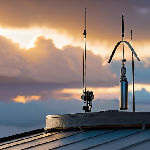
    Stop Guessing and Start Measuring feedline loss.

    At the end of the day, feedline loss isn’t some theoretical concept from a textbook; it’s the physical reality of your signal fighting its way through copper and dielectric. We’ve looked at how frequency climbs, how cable length drags you down, and why your choice of coax can make or break a DX attempt. If you’re running a thin, cheap RG-58 up a twenty-foot mast for 10-meter work, you aren’t just losing signal—you’re throwing money into the dirt. Don’t fall into the trap of thinking a higher-wattage transceiver will compensate for a bad line. You can’t out-power physics, and you certainly can’t out-shout a bad connection once that energy has already bled off into heat inside your cable jacket.

    I know it’s tempting to just plug everything in and hope for a miracle when the band opens, but there is a specific kind of satisfaction in knowing exactly what your system is capable of. When you finally hear that distant station through the noise, and you know it’s because your feedline is efficient and your antenna is at the right height, it feels different. It’s not luck; it’s engineering. So, grab your wattmeter, check your cables, and respect the physics of your station. Once you stop guessing and start measuring, you stop being a passenger in your own hobby and start actually controlling the airwaves.

    Frequently Asked Questions

    If I switch from RG-58 to something thicker like LMR-400, am I actually going to notice a difference on the 20m band, or is it just extra weight in my pack?

    If you’re running a short run from a rig to a desk, you won’t see much. But if that coax is stretching 50 feet up a tree to a dipole on 20m, the difference is massive. I’ve measured the drop; switching from RG-58 to LMR-400 on a decent run can reclaim nearly a full SWR-corrected decibel. That’s the difference between a weak signal and a solid contact. If you’re portable, it’s heavy, but it’s not just dead weight.

    Does a high SWR in my line actually increase the loss, or am I just losing power to heat in the transmitter?

    It’s both, and that’s where people get tripped up. If you have a high SWR, you’re losing power in two distinct ways. First, you’re losing energy to heat inside the transmitter’s final stage because the reflected power is pushing back against the circuitry. Second, that mismatch can actually change how the cable behaves, potentially increasing attenuation. You aren’t just losing signal to the air; you’re literally cooking your rig and wasting juice in the coax.

    How much does the length of my cable really matter if I'm only running a low-power QRP setup?

    It matters more than you think. When you’re running 5 watts, a 3 dB loss isn’t just a minor annoyance—it’s literally cutting your output power in half. If you’re using fifty feet of cheap RG-58 to get up to a tree, you might be throwing away two watts before the signal even sees the antenna. In QRP, your margin for error is razor-thin. Don’t let a long, mediocre cable turn your precious 5 watts into a pathetic 2.

  • High Swr: How to Find the Cause in Order

    High Swr: How to Find the Cause in Order

    I was halfway up a ridge in the Cascades last autumn, sweat soaking through my shirt and my pack feeling twice its weight, when my SWR meter suddenly spiked into the red. I had spent three hours tuning that dipole to perfection in my backyard, only to have it fall apart the moment I actually tried to use it. Most manuals will tell you to just “check your connections,” but when you’re staring at a reading that makes no sense, you need more than a generic suggestion. Learning how to troubleshoot high swr isn’t about following a checklist of obvious steps; it’s about understanding the physical reality of your antenna system and how the environment is fighting you.

    In this guide, I’m skipping the textbook fluff and getting straight to the measurements that actually matter. We aren’t just going to guess which piece of coax is failing; we are going to use real tools to isolate whether your problem is a bad solder joint, a moisture-wicking connector, or an antenna that’s simply too low to the ground to function. I’ll show you how to stop the endless cycle of swapping parts and start finding the actual source of your reflected power, so you can spend less time staring at a meter and more time making contacts.

    Table of Contents

    Guide Overview

    Total Time: 1-4 hours
    Estimated Cost: $0-50
    Difficulty: Intermediate

    Tools & Supplies

    • SWR/Wattmeter to measure standing wave ratio and power
    • Multimeter to check continuity and resistance in cables
    • Visual Inspection to check for physical damage or corrosion
    • Replacement Coaxial Cable (if existing cable is damaged)
    • Dielectric Grease (small amount for connector protection)

    Step-by-Step Instructions

    • 1. First things first: stop looking at the SWR meter on your radio and get a dedicated antenna analyzer. Most built-in meters are just glorified voltage detectors that tell you something is wrong, but they won’t tell you where it’s wrong. I want to see the impedance curve. If you can’t see the resonance point shifting as you move along the line, you’re just guessing in the dark, and guessing is how you accidentally fry a final transistor.
    • 2. Isolate the coax from the antenna. This is the simplest test, but people skip it because they think they’re being clever. Disconnect your feedline from the antenna and check the SWR at the end of the cable. If the SWR is still high, the problem is in your cable, connectors, or the radio itself. If it drops to a perfect 1.1:1, then you know the coax is fine and your headache is actually up in the wires.
    • 3. Inspect your connections with more than just your eyes. I’ve seen plenty of “perfect” looking PL-259 connectors that had a single strand of braid touching the center conductor. Use a magnifying glass if you have to. If you find a connector that looks suspicious, don’t just tighten it; cut it off and re-terminate it. A loose connection creates a high-impedance point that will drive your SWR through the roof every single time.
    • 4. Check your antenna’s physical geometry. If you’re running a wire antenna, check for any sagging or contact with nearby objects. I once spent three hours chasing an SWR spike only to realize a tree branch had grown into my dipole during a summer storm. If your antenna is near a metal roof, a fence, or even a heavy pile of wet gear, the capacitive coupling is going to shift your resonant frequency and mess up your readings.
    • 5. Measure the height. This is where most people get it wrong. An antenna that looks perfect on a bench in my workshop will behave completely differently when I’ve got it mounted 15 feet up a pole in a field. If your SWR is high, check if the antenna is too close to the ground or a structure. The proximity to “earth” or metal changes the ground plane, and without the right height, your impedance matching will never be stable.
    • 6. Look for moisture ingress. If you’ve been operating in the rain or high humidity, check your antenna elements and connector housings for water. Water inside a coax cable is a nightmare because it changes the dielectric constant, which effectively changes the velocity factor of the cable. If your SWR was fine yesterday but is spiking today after a storm, you likely have a leak that’s turning your feedline into a giant, lossy capacitor.
    Is It Real Why Vswr Meter Calibration Actually Matters

    Is It Real Why Vswr Meter Calibration Actually Matters

    I’ve seen it a dozen times: someone spends three hours climbing a mast to adjust a dipole, only to come back down frustrated because their meter is screaming 3:1, when the antenna is actually fine. The problem isn’t the wire; it’s that they’re trusting a tool that hasn’t been verified in years. VSWR meter calibration isn’t just some academic formality; if your meter’s internal reference is off, you’re chasing ghosts. I always start by checking my meter against a known load or a calibrated dummy load before I even touch the antenna tuner. If the baseline is wrong, every single reading you take thereafter is just a lie told by a piece of hardware.

    When you’re actually using an antenna analyzer, remember that the device is only as good as its connection to the system. A tiny bit of oxidation on a connector can mimic a massive radio frequency signal reflection, making you think you have a fundamental impedance mismatch when you really just have a dirty N-type connector. Don’t let a faulty reading drive you to replace a perfectly good feedline. Check your connections, verify your calibration, and then—and only then—start looking for the real culprit.

    Hunting Impedance Mismatch Causes Without the Guesswork

    Hunting Impedance Mismatch Causes Without the Guesswork

    When you move past the basic meter readings and start actually hunting for the source of the problem, you have to stop thinking about “bad antennas” and start thinking about impedance mismatch causes. Most of the time, it isn’t the wire itself that’s failing; it’s the transition points. I’ve spent more afternoons than I care to admit tracing a high SWR back to a single, tiny bead of moisture that worked its way into a PL-259 connector. If you aren’t using an antenna analyzer to look at the impedance curve across the band, you’re essentially flying blind. A simple SWR reading tells you something is wrong, but an analyzer tells you where the mismatch is happening—whether it’s a capacitive loading issue or a physical break in the line.

    Don’t skip the boring stuff, either. I’ve seen people buy a brand-new dipole only to realize their “new” coax has a crushed dielectric somewhere in the middle. Checking coaxial cable integrity is a non-negotiable step. If you can, use a Time Domain Reflectometer or even a cheap TDR function on a modern analyzer to see exactly how many meters down the line the reflection is occurring. It turns a three-hour guessing game into a five-minute fix.

    Five Things to Check Before You Start Tearing Your Shack Apart

    • Stop looking at the radio and start looking at the connection points. I’ve lost count of how many times I’ve spent an hour cursing a “bad antenna” only to find a tiny bit of oxidation on a PL-259 connector or a slightly loose center pin. Clean your contacts, tighten your connections, and if you’re using cheap crimp connectors, just stop—replace them with something that actually holds.
    • Check your coax for more than just breaks. It’s easy to spot a crushed cable, but it’s much harder to spot moisture ingress. If you’ve got a cable that’s been sitting in a damp garden or a poorly sealed weatherproofing boot, the dielectric might be compromised. I once spent a whole afternoon chasing a phantom SWR spike only to realize my coax had turned into a sponge after a heavy rain.
    • Remember that your antenna doesn’t exist in a vacuum. If you’ve moved your setup, even by a few feet, you might have changed the ground plane or brought it too close to a metal structure. I’ve seen SWR climb because someone decided to mount a dipole too close to a metal gutter or a shed roof. If you change the environment, you change the impedance.
    • Test the components individually if you can. If you have a tuner, bypass it to see if the SWR is coming from the antenna or if the tuner itself is failing to match. If you have a spare piece of coax, swap it out. Don’t try to solve the whole puzzle at once; isolate the variables so you aren’t chasing your tail.
    • Don’t ignore the height. I know, I know, I always say this, but if you’ve lowered your antenna or moved it closer to the ground, your SWR is going to shift. An antenna that was perfectly matched at 10 meters above ground is going to look completely different at 3 meters. If you change the height, you change the physics. Measure the height, then check the SWR.

    The Bottom Line Before You Hit the Shack

    Stop chasing phantom SWR readings without first verifying your meter is actually calibrated; a false reading is just a way to waste an afternoon and money on parts you don’t need.

    Always remember that height above ground is a variable, not a constant—an antenna that looks perfect on your bench might behave entirely differently once you’ve actually hoisted it up the tree.

    If your SWR is spiking, look for the physical reality of the mismatch—check the connectors, the coax integrity, and the feedpoint—rather than just blindly turning an antenna tuner knob and hoping for the best.

    ## Stop Chasing Ghosts

    Don’t let a digital readout bully you into thinking your antenna is broken when it’s really just your coax being crushed or a connector that’s more oxidation than copper. Before you tear down your entire feedline, grab a real analyzer and find out if you’re actually fighting an impedance mismatch or if you’re just reading the ghost of a bad connection.

    Wren Castellano

    Getting Back on the Air

    Troubleshooting antenna SWR: Getting Back on the Air.

    At the end of the day, troubleshooting SWR isn’t about memorizing a flowchart; it’s about moving systematically from the rig to the radiator. We’ve looked at why your meter might be lying to you, how to distinguish a genuine mismatch from a calibration error, and why you need to stop swapping components blindly and start actually measuring the impedance. Remember, if your SWR is spiking, it’s usually something physical—a bad connector, moisture in the coax, or an antenna that’s simply not seeing the ground it needs. Don’t let a high reading frustrate you into thinking your hardware is junk; most of the time, it’s just a mechanical failure waiting to be found with a bit of patience and a decent analyzer.

    Radio is a physical medium, and it doesn’t care about what the manual says if the real-world conditions say otherwise. There is a specific kind of satisfaction that comes from finding that one corroded lug or realizing your dipole is just six inches too short for the band you’re chasing. It’s easy to get caught up in the digital perfection of modern SDRs, but the fundamentals of electromagnetics haven’t changed since I was fifteen. Keep your tools sharp, keep your measurements honest, and trust the data over the guesswork. Once you get that SWR down and the signal finally clears the noise floor, you’ll remember exactly why we do this.

    Frequently Asked Questions

    I’ve checked my coax and the antenna looks fine, but my SWR still jumps every time I key the mic—could it be an issue with my ground plane or just a bad connection in the connector?

    If it jumps when you key the mic, you’re likely looking at a mechanical or electrical instability. Check your connectors first; a loose center pin or a braid that isn’t properly crimped can create a capacitive gap that shifts under load. If the connectors are solid, look at your ground. If you’re using a mobile mount or a portable setup without a decent ground plane, the antenna’s impedance is essentially floating, and your body or the chassis might be part of the circuit.

    If my SWR is low at the antenna but spikes at the rig, am I looking at a cable problem or is there something else happening in the feedline?

    If you’re seeing a low SWR at the antenna but a spike at the rig, you aren’t looking at an antenna problem; you’re looking at a transmission line problem. Something is eating your signal between point A and point B. It’s usually a bad connector, water ingress in the coax, or a sharp bend that’s crushed the dielectric. Grab your analyzer and test the line in sections. Don’t just swap the whole run until you’ve found the leak.

    Is it actually worth trying to tune a dipole if I'm mounting it only five feet off the ground, or am I just fighting a losing battle against the ground effect?

    Look, if you’re only five feet up, you aren’t just fighting the ground effect; you’re practically living in it. At that height, the ground is part of your antenna system, and it’s a messy, capacitive part. You can tune that dipole until your eyes bleed, but the impedance is going to shift the second you move a single foot or the soil moisture changes. Don’t waste your afternoon chasing a perfect SWR—just get a good tuner and accept the reality of your setup.

  • How to Pick a Battery for a Day in the Field

    How to Pick a Battery for a Day in the Field

    I was three miles up a ridge in the Catskills last October, staring at my transceiver’s dying display, when I realized my “high-capacity” brick was nothing more than a glorified paperweight. I had spent forty minutes calculating my link budget, only to be undone because I trusted a shiny sticker instead of a load test. Most people approach learning how to pick a portable power bank by reading the marketing fluff on the box, but if you’re running sensitive RF gear or even just a modern smartphone, those mAh ratings are often total fiction. They tell you what the cells can hold in a vacuum, not what they can actually deliver when the voltage starts to sag under a real load.

    I’m not here to sell you on a specific brand or repeat the same tired specs you’ve seen on every retail site. Instead, I’m going to show you how to look past the glossy packaging and focus on the metrics that actually matter: voltage stability, discharge rates, and real-world efficiency. I’ve put these units through the ringer with my own test gear, and I’ll tell you exactly which ones hold their line and which ones are just expensive junk waiting to fail you when you’re off the grid.

    Table of Contents

    Mah vs Wh Explained Why Marketing Numbers Are Often Lies

    Mah vs Wh Explained Why Marketing Numbers Are Often Lies

    If you’re looking at the back of a box and only seeing a massive number followed by “mAh,” you’re being sold a half-truth. Manufacturers love milliamp-hours because it’s a big, shiny number that looks impressive on a retail shelf, but it’s a mathematically incomplete metric. The problem is that mAh doesn’t tell you anything about the energy density or the voltage at which that capacity is being delivered.

    To actually understand what you’re carrying in your pack, you need to look at the Wh (Watt-hours). This is where the real math happens. A 10,000mAh battery at 3.7V is a very different beast than a 10,000mAh battery at a higher voltage. When I’m planning a weekend of portable operating, I don’t care about the milliamp count; I care about the total energy budget. If you’re trying to calculate how many hours your SDR or transceiver will run before the lights go out, stop looking at the mAh and start calculating the Wh. It’s the only way to get a realistic sense of your runtime versus the portable battery weight and size you’re forced to lug up a ridge.

    Lithium Ion vs Lifepo4 Comparison Measuring Real Battery Cycle Life

    Lithium Ion vs Lifepo4 Comparison Measuring Real Battery Cycle Life

    Most manufacturers will push Lithium-ion (Li-ion) because it’s light and cheap to mass-produce, which is great if you’re just charging a phone on a train. But when I’m packing for a weekend on a ridge, I look at the chemistry differently. Li-ion cells are fine, but they’re temperamental; they don’t like being drained to zero, and they definitely don’t like heat. If you’re looking for a long-term investment, a lithium ion vs lifepo4 comparison shows a massive gap in longevity. I’ve seen Li-ion packs start to lose their “oomph” after maybe 300 to 500 cycles, whereas LiFePO4 cells can often push past 2,000 cycles without breaking a sweat.

    The trade-off is almost always portable battery weight and size. LiFePO4 is significantly heavier and bulkier for the same amount of energy stored. If you’re hiking five miles to a summit, that extra pound in your pack matters. However, if your goal is a stationary setup or something that sits in your kit for years, the battery cycle life of LiFePO4 makes it the clear winner. I choose my chemistry based on the mission: Li-ion for the lightweight sprint, LiFePO4 for the long haul.

    Stop Guessing and Start Measuring: 5 Rules for Real-World Power

    • Look at the discharge curve, not just the capacity. A power bank might claim 20,000mAh, but if the voltage sag is aggressive once you hit a 2A load—like when your SDR or handheld rig starts pulling peak current—that capacity is useless. I’ve seen banks that look great on paper but drop below usable voltage the second you actually try to do work with them.
    • Check the actual output voltage stability. If you’re powering sensitive radio gear or a laptop, you don’t want a unit that fluctuates wildly every time the internal regulator struggles. I always check if the output stays within a tight tolerance; if the manufacturer won’t list the ripple or voltage regulation specs, they’re likely hiding a cheap, noisy circuit.
    • Factor in the conversion tax. You aren’t getting 100% of that rated capacity into your device. Between the heat loss in the boost converter and the inherent inefficiency of moving energy from 3.7V internal cells up to 5V or 12V, you’re realistically looking at about 65-75% efficiency. If you need 40Wh of actual energy for a long weekend on a hill, don’t buy a 40Wh bank; buy a 60Wh one.
    • Prioritize port versatility over “fast charging” buzzwords. I don’t care if it claims to charge a phone in twenty minutes if it doesn’t have a stable USB-C PD (Power Delivery) output that can negotiate the correct voltage for your specific gear. Make sure it has enough high-draw ports to handle your primary device and your backup without the whole unit overheating and thermal-throttling into oblivion.
    • Weigh the trade-off between density and durability. High-density lithium-polymer packs are great for keeping your pack weight down on a hike, but they’re finicky. If you’re roughing it in the field, a slightly heavier LiFePO4-based unit or a more robustly encased cell is worth the extra grams because it won’t quit on you just because the temperature dropped ten degrees or you bumped it against a rock.

    The Bottom Line Before You Pack Your Bag

    Stop obsessing over the mAh rating on the sticker; look at the Watt-hours (Wh) instead, because that’s the only number that actually tells you how much work your radio can do before the voltage sags and your rig shuts down.

    If you’re planning a multi-day trek, prioritize LiFePO4 cells even if they’re heavier; I’ve measured the discharge curves, and they hold a steady voltage long after standard Lithium-Ion packs start dropping off and leaving you with nothing but a dead transceiver.

    Always budget for a 20% loss in capacity due to heat and conversion inefficiency—if your math says a pack will run your rig for five hours, expect four, especially if you’re operating in the sun or using a high-draw SDR.

    The Voltage Trap

    Stop obsessing over the mAh printed on the side of the casing; that number is a marketing abstraction that assumes a perfect world. If you’re out on a ridge trying to keep a transceiver alive, you need to look at the Wh and the actual voltage sag under load. I’ve seen plenty of “high-capacity” bricks that look great on paper but drop their voltage the second you hit the PTT, leaving you with nothing but a dead radio and a long walk back down the hill.

    Wren Castellano

    Stop Guessing and Start Measuring

    Stop Guessing and Start Measuring battery capacity.

    At the end of the day, picking a power bank for your field kit isn’t about finding the biggest number on the sticker; it’s about finding the one that actually holds its line when the load gets heavy. I’ve learned the hard way that a high mAh rating means nothing if the voltage sag kills your SDR or prevents your transceiver from hitting its rated output. You need to look past the marketing fluff and prioritize real-world Wh ratings and chemistry that can handle the cycles. Whether you go with the high energy density of Lithium Ion or the rugged longevity of LiFePO4, make sure you’re testing for actual capacity under load before you trust that battery to be your lifeline on a remote ridge.

    Radio is about being prepared for the variables we can’t control—the shifting ionosphere, the sudden rain squall, or the terrain that eats your signal. Your power source shouldn’t be another variable you’re sweating over. When you build a kit based on measurements rather than hearsay, you gain something more valuable than just extra runtime: you gain predictability. There is a quiet, immense satisfaction in sitting out on a hill, knowing exactly how many hours of operation you have left because you did the math beforehand. So, go out there, test your gear, and then get on the air.

    Frequently Asked Questions

    If I'm running a high-draw SDR or a portable transceiver, how much does the actual voltage sag matter when the battery gets below 20%?

    It matters more than most people realize. When you’re pushing a high-draw transceiver, that voltage sag isn’t just a number on a display; it’s the difference between a clean signal and a rig that resets every time you key the mic. I’ve seen SDRs lose their lock on a signal simply because the voltage dipped below the regulator’s threshold. If you’re below 20%, don’t trust the “remaining time”—trust your voltmeter.
    Is there a real-world difference in efficiency between a power bank with built-in AC inversion versus just running straight DC through a buck-boost converter?

    Look, if you’re trying to squeeze every minute of operating time out of a small pack, stay away from the built-in AC inverters. They are incredibly inefficient. You’re taking DC, converting it to AC, and then your rig’s power supply is converting it right back to DC. You’re losing massive amounts of energy to heat in that middle step. Run straight DC through a decent buck-boost converter instead; it’s much cleaner and far more efficient.

    How much "phantom drain" should I expect to lose just by leaving the power bank in my pack overnight while it's sitting idle?

    If you’re leaving a decent quality unit in your pack, you shouldn’t see more than a 1-3% drop overnight. If you wake up and you’re down 10%, something is wrong. It’s usually either a cheap protection circuit that isn’t actually “off,” or you’ve got a USB cable plugged in that’s acting like a tiny, parasitic load. I’ve seen mid-range banks bleed out just because their internal voltage regulator stays awake. Check your connections.

  • How to Read a Signal Report and What It Really Tells You

    How to Read a Signal Report and What It Really Tells You

    I remember sitting on a granite outcrop in the Catskills three years ago, shivering in a damp wind, staring at a signal report that said 59 and wondering why my noise floor was screaming. I had spent six hours lugging a wire antenna and a battery pack up that ridge, only to realize I had no idea if I was actually performing or if the solar cycle was just handing me freebies on a silver platter. Most people will tell you that checking your signal report is just about listening for a few decibels of difference, but that’s a half-truth that ignores the reality of your local environment. If you want to actually learn how to check your signal report without getting lost in the jargon, you have to stop treating it like a polite compliment and start treating it like raw data.

    I’m not here to give you the textbook version of signal analysis that ignores ground plane physics or local interference. Instead, I’m going to show you how to look past the courtesy of a “59” and determine if your hardware is actually doing its job. We’re going to talk about distinguishing between a clean signal and a lucky one, and I’ll tell you exactly when you can trust your measurements and when you should just blame the ionosphere.

    Table of Contents

    Decoding Signal Readability Beyond the Three Letter Code

    Decoding Signal Readability Beyond the Three Letter Code

    We’ve all been there: someone drops a “59” on you, you nod like you know exactly what it means, and then you move on. But if you’re serious about understanding RST signal reports, you have to stop treating that three-digit code like a magic number. The “R” is for readability, and it’s the most subjective part of the whole equation. I’ve sat on ridges where a “5” felt like a solid, clear signal, only to realize later that my local noise floor was so low it was masking a mediocre incoming wave. You aren’t just listening to the voice; you’re listening to the signal-to-noise ratio.

    When you’re decoding signal readability, you need to look past the courtesy of the operator. A “4” might mean the signal is loud but buried in static, or it might mean the audio is so distorted by a cheap amplifier that you’re working harder than you should be. I always tell my students to look for the “why” behind the number. Is the signal fading because of a moving tropospheric duct, or is your antenna just poorly tuned for that specific frequency? If you can’t distinguish between a weak signal and a noisy one, you aren’t actually reading the report—you’re just guessing.

    Understanding Rst Signal Reports Without the Old Wives Tales

    Understanding Rst Signal Reports Without the Old Wives Tales

    Look, we’ve all been there—sitting in the shack, hearing a faint, crackly voice through the noise floor, and instinctively shouting “59” because it feels like the polite thing to do. But if we’re actually talking about understanding RST signal reports with any degree of engineering integrity, we have to stop treating those two digits like a courtesy instead of a measurement. The ‘R’ is your readability, and the ‘S’ is your signal strength. When I’m out on a ridge with a wire antenna only six meters off the ground, a “5” for strength might be a total fluke of local terrain rather than a reflection of my actual radiated power.

    If you want to move past the guesswork, you need to separate the two. I’ve seen plenty of operators mistake a high signal-to-noise ratio for high readability. You can have a signal that is screamingly loud—a solid 9 on the strength scale—but if the fading is aggressive or the phase distortion is making the audio sound like a blender, that’s a 2 for readability. Don’t let a loud signal trick you into thinking your radio propagation signal quality is better than it actually is. If it’s hard to pull the words out of the static, call it what it is.

    Stop Taking Their Word For It: 5 Ways to Actually Validate Your Performance

    • Cross-reference your logs with the noise floor. If someone gives you a 5/9 but your SDR shows a local noise floor sitting at -70 dBm, they’re being polite, not honest. You need to know if you’re actually punching through the static or just riding a lucky wave.
    • Watch the trend, not the snapshot. A single signal report is a data point, not a trendline. If you’re getting 5/9s at 14:00 UTC but dropping to 3/3 by 16:00, don’t go buying a new amplifier; your solar cycle or local interference is shifting, and you need to track that timing to understand your real coverage.
    • Use a second station as a benchmark. If you have a buddy on a similar setup, compare notes. If they’re getting 5/7 on the same band you’re hitting 4/4 on, it’s time to stop looking at the ionosphere and start looking at your coax connections or your antenna’s height above ground.
    • Listen to the “ghost” of your signal. When you’re receiving, don’t just listen for the voice; listen for the level of the background radiation. If the signal is strong but the background noise is also spiking, you’re likely dealing with a local RFI issue rather than a truly high-performance contact.
    • Check your SWR vs. your actual report. I’ve seen plenty of people obsess over a perfect 1.1:1 SWR on their analyzer, only to realize their signal reports are mediocre because the antenna is mounted too low to the ground to actually radiate effectively. A pretty number on a meter doesn’t mean a thing if the physics of your installation are working against you.

    The Reality Check: Three Things to Remember

    Stop treating RST like a magic number; a 59 report tells you how you sound, but it doesn’t tell you if your antenna is actually performing or if you just caught a lucky opening.

    Always cross-reference your signal reports with your actual SWR and noise floor—if your signal is dropping but your SWR is dead flat, the problem isn’t your rig, it’s the atmosphere.

    If you’re getting consistent 4s when you should be getting 5s, don’t just assume it’s the ionosphere; check your ground plane and antenna height, because a poorly mounted wire will drag your reports down every single time.

    Stop Trusting the Legend, Start Trusting the Data

    A signal report isn’t a pat on the back; it’s a diagnostic tool. If you’re just nodding along when someone says ’59’ without looking at your actual signal-to-noise ratio or whether your antenna is actually resonant, you aren’t learning anything—you’re just participating in a ritual.

    Wren Castellano

    Bringing it Back to Earth

    Bringing it Back to Earth with data.

    At the end of the day, checking your signal reports isn’t about chasing a perfect 599 every single time; it’s about building a data set that actually means something. Stop treating a signal report like a vague compliment and start treating it like a diagnostic tool. If you’re consistently hearing 4s when you think you’re pushing 5s, it’s time to stop blaming the solar cycle and start looking at your coax, your ground plane, or whether your antenna is actually high enough to clear that treeline. Remember, a report is only useful if you use it to bridge the gap between what you think your station is doing and what the airwaves are actually telling you.

    Radio is a fickle medium, and some nights the ionosphere is going to carry a signal halfway around the world even if your setup is held together with electrical tape and prayer. But when you learn to separate the atmospheric luck from your actual hardware performance, that’s when the real fun begins. Don’t get discouraged by a bad report; get curious about it. There is a quiet, immense satisfaction in tuning an antenna, watching the SWR drop, and then hearing that first clear report confirm that you’ve finally mastered your corner of the spectrum. Now, get out there, get on the air, and see what you can actually do.

    Frequently Asked Questions

    If my signal report is consistently a 59 but my contacts are falling apart, am I looking at a local noise floor issue or a problem with my antenna's radiation pattern?

    If you’re pulling 59s but the conversation is a struggle, you’re likely fighting a high noise floor or a skewed pattern. If the noise is local, your signal might be “strong” simply because it’s riding on a mountain of interference. But if your contacts are dropping, check your radiation pattern; you might be hitting them hard in one direction while your nulls are wide open elsewhere. I’d start by measuring your local noise floor during a quiet window.

    How much of a "good" signal report is actually just me having a high-gain Yagi while the other person is running a wire on the ground?

    That’s the million-dollar question, isn’t it? Honestly, a lot of it. If you’re sitting on a ridge with a 3-element Yagi at 10 meters up and they’re running a random wire draped over a low hedge, your 59 report is lying to you. You aren’t necessarily “better”; you’re just more efficient at capturing the energy. Before you celebrate, look at your SWR and your local noise floor. If you’re just winning on gain, you’re not testing the propagation—you’re just testing your antenna.

    When should I stop trusting the RST numbers I'm getting and start looking at my actual SWR and power output to see if the rig is lying to me?

    If your RST reports start looking like a lottery—one minute a 59, the next a 39—stop looking at the sky and start looking at your coax. If your SWR is creeping up or your power output is dropping while your reports tank, your rig isn’t “having a bad day”; your hardware is failing you. Trust the RST for the channel, but trust your meter for the truth. If the numbers don’t match the physics, the rig is lying.