I was halfway up a ridge in the Catskills last October, shivering in a light drizzle, when my dipole decided to stop playing nice. I had checked the connections three times at the shack, but the SWR was screaming at me like a banshee. Most people will tell you to just re-string the whole thing and hope for the best, but that’s a waste of time and good copper. If you want to actually learn how to find a fault in a wire antenna, you have to stop treating it like a magic wand and start treating it like a circuit. It isn’t just about “bad luck” with the weather; it’s usually a physical break, a salt-crusted insulator, or a connection that’s been slowly vibrating itself to death in the wind.
In this guide, I’m skipping the fluff and the “theory-only” nonsense you find in the old manuals. I’ll show you how to use a simple continuity test and a basic meter to isolate the break without having to tear down your entire station. We’re going to talk about real-world inspection—looking at the insulators, checking the tension, and knowing exactly where to probe. I’ll give you the practical steps to find the failure, so you can spend less time troubleshooting and more time actually making contacts.
Table of Contents
- Step-by-Step Instructions
- Using a Multimeter for Antenna Repair Instead of Luck
- Identifying Coaxial Cable Damage and Signal Loss Causes
- Five Things Your SWR Meter Isn't Telling You
- The Bottom Line Before You Pack Up
- The Myth of the "Glitchy" Antenna
- Don't Just Guess, Go Measure
- Frequently Asked Questions
Guide Overview
Tools & Supplies
- Multimeter for checking continuity and resistance
- SWR Meter or Antenna Analyzer to identify standing wave issues
- Wire cutters for isolating sections
- Electrical tape for marking segments
- Replacement wire or jumper cables for temporary bypasses
Step-by-Step Instructions
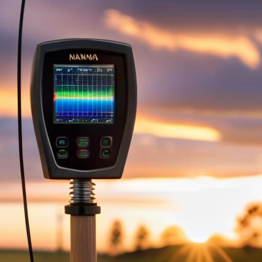
- 1. First, get your SWR meter or NanoVNA out and stop looking at the display like it’s a crystal ball. You need to establish a baseline. If you’re seeing a high SWR, look at the shape of the curve. A sharp, narrow spike usually means you’ve got a physical break or a bad connection somewhere, whereas a broad, messy slope often points to something more subtle, like a nearby object or a change in the ground plane. Don’t just tell me the ratio is 3:1; tell me where the resonance is shifting compared to when the antenna was actually working.
- 2. Check your connections before you start climbing any trees. I’ve lost count of how many times I’ve spent an hour troubleshooting a “broken” antenna only to find a loose lug or a bit of oxidation at the SO-239 connector. Take a decent multimeter, set it to continuity, and test every single junction from the radio output all the way to the antenna feed point. If you have a connection that shows even a few ohms of resistance where it should be zero, that’s your culprit.
- 3. If the connections look solid, it’s time to look for the physical break in the wire. This is where most people get lazy, but you can’t just stare at the wire from the ground and hope for the best. If you can, get a visual inspection under load—though that’s a bit of a misnomer, what I mean is, look for where the wire has been rubbing against a branch or a support rope. Even a tiny nick in the insulation can lead to a high-impedance leak if the humidity is high enough, and insulation failure is often invisible to the naked eye until you’re looking for it.
- 4. Use the “segmentation” method if you’re still stuck. This is the part that requires a bit of patience and a long ladder. If you have a long wire, you can temporarily short out sections of it to see how the SWR responds. If you short the wire halfway down and the SWR suddenly drops to a healthy level, you know the fault is in the second half of that span. It’s a bit of a process, but it’s much faster than replacing the entire length of wire because you were too impatient to isolate the problem.
- 5. Don’t forget to check your insulators and support hardware. I once spent a whole afternoon chasing a phantom SWR issue only to find that a cracked plastic insulator was allowing the wire to leak signal directly into the support pole. If your antenna is suspended by something conductive, or if an insulator has developed a hairline crack, you aren’t running a wire antenna anymore; you’re running a very inefficient, very noisy version of a ground-fed vertical.
- 6. Finally, once you think you’ve fixed it, don’t just pack up and go home. Re-measure everything. I want to see that resonance point move back to exactly where it belongs. And remember, if the SWR looks good but you’re still not making contacts, the problem might not be the wire at all—it might be that the ionosphere is having a bad day, or your ground setup is nonexistent. Always verify the hardware before you start blaming the sun.
Using a Multimeter for Antenna Repair Instead of Luck
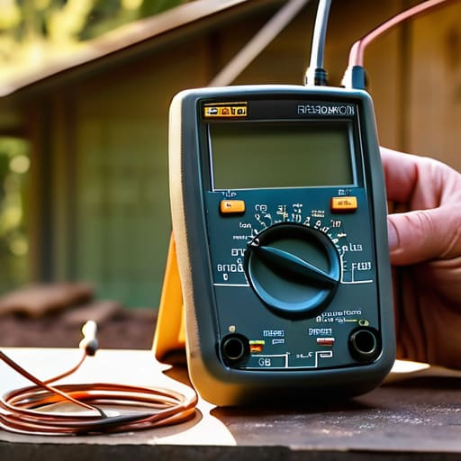
Look, I’ve seen too many operators spend three hours pacing around their backyard, staring at a wire and praying for a miracle, when a five-minute antenna continuity test would have solved the problem. If you’re just poking at the wire with your fingers, you aren’t troubleshooting; you’re guessing. When I’m out on a portable setup and my SWR suddenly climbs, I don’t assume the ionosphere has gone sour—I grab my meter. Start by checking the connection from the feedpoint to the far end of the element. If you aren’t getting a reading, you don’t have a “mysterious signal issue,” you have a break.
While you’re at it, don’t neglect the feedline. A common mistake is assuming the wire is the culprit when the real headache is actually identifying coaxial cable damage hidden under a layer of tree bark or a sharp corner of a fence. Use your multimeter to check for shorts between the center conductor and the shield. If you find a short, you’ve saved yourself from chasing ghosts in the antenna itself. Stop treating your gear like a black box and start treating it like the circuit it actually is.
Identifying Coaxial Cable Damage and Signal Loss Causes
If you’ve confirmed the wire itself is intact, stop looking at the antenna and start looking at the feedline. I’ve lost more contacts to a bad coax connection than I have to actual antenna failure. When you’re identifying coaxial cable damage, don’t just look for obvious kinks or bird bites in the jacket. I once spent an entire afternoon chasing a high SWR only to find that a tiny amount of moisture had wicked into the dielectric through a poorly crimped connector. It wasn’t a broken wire; it was a change in the cable’s characteristic impedance that turned my feedline into a giant, inefficient radiator.
Grab your meter and do more than just a basic continuity check. You need to be inspecting wire insulation and the coax jacket for any sign of degradation or UV damage, especially if you’ve left your setup out on a ridge for a few seasons. If the jacket is brittle or discolored, the dielectric is likely compromised. If you can, use a TDR or even a simple reflectometer to see if the signal is bouncing back from a specific point in the line. If the impedance isn’t where it should be, your power is going into the dirt instead of the air.
Five Things Your SWR Meter Isn't Telling You
- Stop trusting your eyes and start trusting your continuity tester. A hairline fracture in a copper strand might look fine under a flashlight, but it’ll act like a high-impedance resistor the moment you try to push any real current through it. If the meter doesn’t beep, the connection doesn’t exist.
- Check your insulators, not just your wires. I’ve spent too many afternoons on a ridge realizing that a “broken” antenna was actually just a piece of UV-damaged plastic that had turned into a semi-conductor, leaking RF straight into the mounting pole. If it’s brittle, it’s a fault.
- Look for the “hidden” shorts in your connectors. A single stray strand of braid pushed into the center conductor hole is enough to tank your performance, and it won’t always show up as a dead short on a cheap meter. Clean them, crimp them properly, and don’t assume a tight nut means a good connection.
- Mind the ground plane—or lack thereof. If your SWR is drifting wildly, don’t immediately assume the wire is broken; check if your counterpoise or ground setup has shifted. An antenna is part of a system, and if the other half of that system is floating in mid-air because a stake pulled loose, the wire isn’t the problem.
- Watch out for environmental interference that mimics a fault. I once spent two hours chasing a “bad” antenna only to realize a nearby power line was inducing enough noise to make my readings look like a total failure. Before you tear down your rig, make sure the fault isn’t actually just the neighborhood’s electrical grid acting up.
The Bottom Line Before You Pack Up
Stop chasing ghosts in the ionosphere when your SWR is high; if you haven’t checked the continuity of your feedline and the integrity of your connections with a meter, you aren’t troubleshooting, you’re just guessing.
Remember that an antenna’s performance is inseparable from its environment; a perfectly tuned wire at 2 meters above the ground is a completely different beast than the same wire at 10 meters, so always document your mounting height.
Don’t fall into the trap of replacing expensive gear when the fault is usually something mundane like a crushed coax or a corroded lug—measure the physical reality of your setup before you reach for your wallet.
The Myth of the "Glitchy" Antenna
Stop blaming the ionosphere or the weather every time your SWR jumps; the sky might be acting up, but a physical break in your wire doesn’t care about the solar cycle. If you aren’t checking your continuity and looking for the actual point of failure, you aren’t troubleshooting—you’re just guessing.
Wren Castellano
Don't Just Guess, Go Measure
At the end of the day, finding a fault in a wire antenna isn’t about having some magical intuition; it’s about being methodical. You’ve checked the continuity with your multimeter, you’ve inspected the coax for kinks or water ingress, and you’ve looked at the physical insulators to see if they’ve been chewed on by a squirrel or weathered by the sun. If your SWR is still jumping around like a caffeinated kid, stop staring at the screen and start looking at the physical reality of your setup. Remember, an antenna isn’t a theoretical math problem once it’s hanging in a tree; it’s a piece of hardware subject to wind, tension, and gravity. If you haven’t checked the connection at the feed point or verified that your ground plane hasn’t shifted, you haven’t actually finished the job.
There is a specific kind of satisfaction that comes from fixing a broken system with your own hands and a bit of real data. It’s easy to get frustrated when the bands go silent, but that silence is usually just a symptom of a mechanical problem waiting to be found. Don’t let a bad connection or a frayed strand of copper keep you off the air. Get out there, climb the ladder if you have to, and trust your measurements over your assumptions. Once you bridge that gap and hear that first weak signal crackle through the noise, you’ll remember exactly why we bother with the wires and the weight in the first place.
Frequently Asked Questions
If I find a break in the wire but can't see it with my eyes, how do I know if it's a clean snap or just a high-resistance connection that's killing my signal?
If you can’t see the break, stop squinting at the wire and start using your multimeter. Set it to resistance and probe both sides of the suspected area. A clean snap will show you infinite ohms—a total open circuit. But if you’re seeing a few ohms or a fluctuating reading, you’ve got a high-resistance connection, likely oxidation or a fray. That’s actually worse; it’ll turn your signal into heat before it ever hits the air.
My SWR is fine when the antenna is sitting on my workbench, but it goes haywire the second I hoist it up to 15 meters—is that a fault in the wire or just the ground plane being wonky?
That’s a classic case of the environment changing the math. If your SWR is clean on the bench, your wire and connections are likely fine. The problem is that your “bench” isn’t the real world. At 15 meters up, you’re finally interacting with the ground and nearby objects. It’s likely not a “fault,” but a change in impedance caused by proximity to a structure or a lack of a proper radial system. Measure the ground plane, not just the wire.
When I'm out in the field and don't have a full spectrum analyzer, what's the most reliable way to tell if a dip in my signal is a hardware failure or just the ionosphere deciding to take a nap?
Look, if you’re on a hill with nothing but a transceiver and a handheld meter, you have to isolate the variables. First, check your local SWR. If the SWR is steady and your coax looks fine, but the signal vanishes, it’s likely the ionosphere being temperamental. If you want real proof, try a different band or a different mode like CW if you’re on SSB. If the noise floor stays low but the propagation is dead, the sky has just closed for business.