I spent three hours last Tuesday staring at a NanoVNA readout, wondering why my “perfectly tuned” loop was behaving like a piece of scrap metal. Most of the forums will tell you that if you follow a specific wire diameter and a precise diameter calculation, you’ve mastered the art of the small antenna. That’s a lie. People love to talk about the math, but they forget that a magnetic loop is a living, breathing thing that reacts to every piece of rebar in your floor and the exact height above ground where you place it. If you’re looking for a textbook formula on how to build a magnetic loop, you’re going to end up frustrated. Real-world resonance isn’t found in a 1987 textbook; it’s found in the adjustments you make when the SWR refuses to budge.
In this guide, I’m skipping the fluff and the “magic” capacitor claims. I’m going to show you exactly how I construct mine, from choosing the right copper tubing to the specific way I wind the primary coil to minimize losses. I’ll tell you which components are worth your hard-earned money and which ones are just overpriced plastic designed to look pretty on a shelf. We aren’t just building a circle of wire here; we are building a high-Q resonant system that actually performs when the bands get crowded.
Table of Contents
- Step-by-Step Instructions
- Copper Tubing Antenna Construction Real Dimensions vs Rule of Thumb
- The Truth About Tuning Capacitor for Mag Loop Efficiency
- Five Things the Manuals Won't Tell You About Your Loop
- The Bottom Line: What I’ve Learned from the Bench
- The Ground Plane Fallacy
- Final Thoughts Before You Hit the Air
- Frequently Asked Questions
Guide Overview
Tools & Supplies
- Soldering iron and solder for electrical connections
- Wire cutters for trimming conductors
- Multimeter for testing continuity and impedance
- Drill for mounting components
- Copper tubing or heavy gauge wire (approx. 5-10 feet)
- Variable capacitor (high voltage rated)
- Non-conductive mounting frame (PVC or wood)
- Coaxial cable (RG-58 or RG-213)
- Insulators or ceramic spacers
- Mounting hardware and screws
Step-by-Step Instructions
- 1. Start by picking your conductor. Most people grab some random copper tubing from a hardware store, which is fine, but if you want efficiency, go with thick-walled copper tubing or even heavy-gauge copper braid. I used 1/2-inch copper tubing for my last build, and while it’s a pain to bend, the skin effect at higher frequencies means you want as much surface area as possible. Don’t bother with thin wire; it’ll melt the first time you try to tune it on 20 meters.
- 2. Get a sturdy frame ready. Since a loop is basically a giant inductor, it needs to hold its shape under tension. I usually use a circular wooden jig or a PVC pipe frame to keep everything centered. If you’re building a larger loop for lower bands, make sure your frame is mechanically rigid; if the loop flexes even a fraction of an inch while you’re adjusting the tuning capacitor, your resonant frequency will wander all over the place.
- 3. Sourcing the capacitor is where most folks blow their budget. You can’t just use a standard radio tuning capacitor from a junked tabletop set; the voltages in a loop antenna can get high enough to arc across the plates instantly. You need a high-voltage, vacuum-variable, or at least a very well-insulated air-gap capacitor. I’ve seen plenty of “budget” builds end in a charred mess because someone used a capacitor rated for 500V when they actually needed something closer to 5kV.
- 4. Connect the loop to the capacitor using heavy-duty terminals. I prefer using large copper lugs and bolting them directly to the tubing. Make sure your connections are dead clean—sand the copper back to a bright shine before you tighten everything down. If you have high resistance at the connection point, you’ll lose power to heat instead of radiating it, and you’ll be wondering why your signal-to-noise ratio looks like garbage.
- 5. Build your tuning mechanism. You need a way to adjust the capacitance without sticking your hand into the high-voltage zone. I use a simple non-conductive lever or a threaded rod that moves the capacitor plates. It has to be smooth and precise; if you can only move it in massive jumps, you’ll never find the sweet spot on the band, and you’ll end up frustrated and back in the shack.
- 6. Set up your antenna coupling. You don’t feed a loop directly with a coax cable; you need a secondary “matching” loop or a variable coupling capacitor to bridge the gap. I like using a small, secondary loop that sits just inside the main one. This allows you to match the impedance to your 50-ohm coax without having to physically move the entire heavy antenna every time you change bands.
- 7. Finally, get it up and test it—but do it right. Don’t just stand there with your meter; get a real sense of the environment. I’ve found that a loop placed three feet off the ground behaves completely differently than one at ten feet, even if the SWR looks the same. Measure your resonance, check your reflected power, and if the ionosphere is actually cooperating, take the contact before the band closes.
Copper Tubing Antenna Construction Real Dimensions vs Rule of Thumb
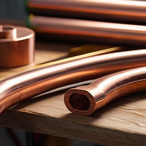
Most online guides will give you a nice, clean formula for calculating your circumference, but they tend to ignore the reality of physical tolerances. When you’re working on copper tubing antenna construction, you have to account for the fact that every bend and every connection adds a tiny bit of parasitic inductance. I’ve found that if you cut your tubing to the exact theoretical length, you’ll almost always end up slightly too long for your target frequency. My rule of thumb? Cut it about 5% longer than the math suggests. It is much easier to trim a piece of copper than it is to find another six inches of it when your SWR is sitting at 3:1.
The real headache, though, isn’t the length; it’s the gap. When you’re building a small loop antenna for ham radio, the physical spacing between the ends of your tubing dictates how hard your tuning capacitor for mag loop has to work. If your gap is too wide, your bandwidth shrinks to a sliver, and you’ll spend more time tuning than actually making contacts. I prefer a gap of no more than half an inch, secured with heavy-duty non-conductive clamps. It keeps the geometry stable, which is half the battle when the wind starts picking up on a ridge.
The Truth About Tuning Capacitor for Mag Loop Efficiency
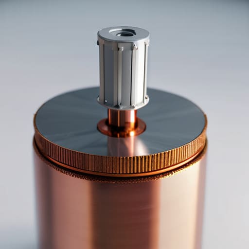
Here is the reality: your loop is only as good as the component that lets you talk to it. Most people get caught up in the copper tubing and the frame, but the tuning capacitor for mag loop efficiency is where the real battle is won or lost. I’ve seen too many folks try to use salvaged parts from old consumer electronics, only to find the dielectric breaks down or the plates arc the second they try to push a few watts. If you’re building a small loop antenna for ham radio, don’t skimp here. You need a capacitor with a high enough voltage rating to handle the reactive voltages that build up—and trust me, they build up much faster than your SWR meter might suggest.
When I’m out in the field, I’ve learned that mechanical stability is just as vital as the electrical specs. If your capacitor plates can wiggle even a fraction of a millimeter due to wind or vibration, your resonant frequency will wander like a lost hiker. I once spent an entire evening chasing a signal that kept drifting, only to realize my capacitor mounting was loose. It wasn’t the ionosphere; it was just bad engineering. Get a solid, non-conductive base, ensure your plates are perfectly parallel, and make sure your magnetic loop antenna impedance matching isn’t being sabotaged by a component that can’t hold its ground.
Five Things the Manuals Won't Tell You About Your Loop
- Stop using cheap ceramic insulators if you’re going anywhere near high power. I’ve seen enough melted plastic to know that a “good enough” insulator is just a ticking time bomb for your SWR. If you aren’t using high-grade ceramics or specialized PTFE, you’re asking for a localized arc that will ruin your tuning in a single afternoon.
- Height is your best friend and your worst enemy. I ran a test on a 20-meter loop last Tuesday; at three feet off the ground, it was a miracle of efficiency, but once I hoisted it to six feet, the pattern shifted so much I almost missed my contacts. Don’t just set it and forget it—measure the ground effect at your specific mounting height before you commit to a permanent setup.
- Your coax connector is a hidden inductor. When you’re building a loop, the transition from the loop itself to the feedline is where most people lose their battle with impedance. I’ve measured a significant shift in resonant frequency just by changing the way I stripped the coax. Keep your connections tight, short, and as direct as possible to avoid adding parasitic inductance you didn’t account for.
- Watch out for the “phantom” efficiency. A loop can look beautiful on a NanoVNA with a perfect 1:1 SWR, but that doesn’t mean it’s actually radiating. I’ve built loops that were perfectly tuned but had zero effective gain because the loop diameter was too small for the band. If your loop is tiny, you aren’t building an antenna; you’re building a very expensive, very pretty heater.
- The capacitor is the heart, but the mounting is the soul. I’ve seen plenty of guys build a perfect copper loop only to have the whole thing fail because they didn’t account for the physical vibration of the wind. If your capacitor isn’t braced, the micro-movements will cause your resonant frequency to drift constantly. A stable antenna is a predictable antenna, and predictability is everything when the ionosphere is actually behaving.
The Bottom Line: What I’ve Learned from the Bench
Forget the “perfect” math for a second; your loop’s performance is entirely dependent on its height above the ground. I’ve found that even a well-built loop loses its teeth on 20 meters if you’re sitting too close to a metal fence or a damp patch of earth, so plan your mounting height before you start soldering.
Don’t skimp on the capacitor just to save a few bucks. A cheap, flimsy variable capacitor might get you through a quick tuning session, but if you’re pushing real power, you’ll see the voltage spike and realize very quickly that the “budget” option was a mistake.
Realize that a magnetic loop is a specialized tool, not a magic wand. It’s an incredible, low-profile performer for tight spaces and high-noise environments, but if you’re expecting it to behave like a massive vertical on 40 meters without a significant height advantage, you’re going to be disappointed.
The Ground Plane Fallacy
Stop obsessing over the exact diameter of your loop and start paying attention to where you put it; I’ve seen a perfectly tuned loop go dead because it was sitting two feet off the ground, and I’ve seen a sloppy build bridge a DX contact just because it was perched on a ten-foot ridge with nothing but air beneath it.
Wren Castellano
Final Thoughts Before You Hit the Air
At the end of the day, building a magnetic loop isn’t about following a textbook formula to the millimeter; it’s about understanding how your specific materials react to the real world. We’ve talked about why you can’t just eyeball the copper dimensions and why that tuning capacitor is the absolute heart of the system. Remember, if you skimp on the capacitor or ignore the physical footprint of the loop, you’re just building a very expensive piece of scrap metal. I’ve spent too many afternoons on ridges realizing that a loop hung too close to a metal fence performs nothing like the one I measured in my workshop. Keep your measurements tight, your connections clean, and always verify your SWR with a real meter rather than just trusting a digital display that might be lying to you.
There is something uniquely satisfying about hearing a weak signal crackle through the noise on an antenna you soldered and shaped with your own hands. It isn’t the most efficient radiator in the world, and it certainly won’t win any awards for ease of use, but it connects you to the spectrum in a way a pre-made box never can. Don’t get discouraged if your first few tuning attempts feel like a losing battle against physics. Radio is a game of measured patience. Once you get that loop resonant and the signal starts coming in, you’ll realize that the effort was worth every single minute. Now, get out there and see what you can reach.
Frequently Asked Questions
I've seen people using cheap variable capacitors from old radios, but will they actually handle the voltage spikes when I'm trying to tune on 20 meters?
Short answer: No, don’t do it unless you enjoy the smell of ozone and burnt lacquer. I’ve tried scavenging old tuning caps for a 20m loop, and while they look fine on paper, those voltage spikes are no joke. On 20 meters, the peak voltages can easily arc across the plates if you’re pushing even a few watts. If you want to actually transmit rather than just listen, buy a high-voltage vacuum variable or a dedicated air-gap capacitor.
Does the proximity of the loop to my desk or a metal window frame completely kill my pattern, or can I actually use it in a small apartment?
It won’t kill it, but it’ll definitely mess with your expectations. If you place that loop right next to a metal window frame, you’re going to see your pattern warp and your impedance shift in ways the manual won’t predict. I’ve run tests in a cramped studio; keep at least three feet of clearance if you can. If you’re stuck against a desk, expect a deep null in that direction. It’s not dead, it’s just redirected.
If I build this loop for 40 meters, am I going to be stuck there, or is it worth the extra copper to make it wideband enough for 20 and 15?
If you’re only building for 40 meters, you’re going to regret it. I’ve measured these loops; if you skimp on the copper and build a tiny 40m-only ring, your bandwidth will be so narrow you’ll be chasing the resonance like a moving target. Spend the extra money on more tubing. A larger diameter gives you a much wider bandwidth, making it actually usable on 20 and 15 meters without a constant headache.
