Category: Antennas

  • Random Wire Antennas: the Cheapest Way Onto Hf

    Random Wire Antennas: the Cheapest Way Onto Hf

    I spent most of last Tuesday on a ridge in the Blue Ridge Mountains, shivering slightly and wondering why I ever thought a three-hour hike was a good idea for a radio session. As I was untangling a mess of wire from a tree limb, I realized how much misinformation is out there regarding what is a random wire antenna. Most of the forums will tell you it’s some sort of “magic” solution for people who can’t be bothered to tune a dipole, or they’ll drown you in complex math that assumes you’re living in a vacuum. In reality, it’s just a piece of conductor that doesn’t follow a specific resonant length, and if you treat it like a black box of mystery, you’re going to have a very frustrating time when the SWR spikes.

    I’m not here to sell you a proprietary matching network or recite a textbook that hasn’t been updated since the Reagan administration. My promise to you is simple: I’m going to tell you exactly how these things behave when they are hung at ten meters above ground and how much of your success depends on the tuner versus the actual physics of the wire. We’ll look at the real-world trade-offs, the gear that actually works, and when you should stop tinkering and just start listening.

    Table of Contents

    The Truth About Electrically Short Antenna Performance
    The Truth About Electrically Short Antenna Performance.

    Here is the reality that the textbooks usually gloss over: when you use an electrically short antenna, you aren’t just dealing with a lack of length; you’re dealing with a massive mismatch in physics. Because the wire is significantly shorter than a quarter-wavelength, its capacitive reactance goes through the roof. This is why people get frustrated when they see a massive SWR reading on their display. It’s not that the wire isn’t “working,” it’s that the energy has nowhere to go because the antenna hasn’t established a proper relationship with the ground.

    This is where the antenna tuner necessity becomes non-negotiable. You can’t just plug a random length of copper into a transceiver and expect magic. You need a tuner to force that impedance into something your rig can actually handle, but—and this is the part I’ve learned the hard way—a tuner is not a substitute for a decent RF ground system. If you don’t provide a counterpoise or a solid ground, your tuner will spend all its time fighting the stray capacitance of your coax, and you’ll end up with more RF in your shack than out of your antenna.

    Hf Radio Antenna Basics vs Real World Physics

    Hf Radio Antenna Basics vs Real World Physics

    Look, the textbooks will tell you that an antenna needs to be a resonant half-wave or a quarter-wave to work efficiently. That’s fine for a classroom, but in the real world, we often deal with lengths that don’t play by those rules. When you’re working with an electrically short antenna, you aren’t just fighting the physics of the wire; you’re fighting the physics of the space around it. A wire that’s too short for the band you’re targeting is going to have a very high capacitive reactance, and that’s where the math meets the mud.

    This is why people get obsessed with impedance matching for random wire setups. You can’t just plug a mismatched length of copper into a transceiver and expect a miracle. You’re going to need an antenna tuner—and I mean a real, beefy one, not a cheap toy—to bridge that gap. But even with a tuner, don’t forget that your RF ground system is doing half the work. If you don’t have a decent counterpoise or a solid ground, that tuner is just going to be working overtime to compensate for a massive imbalance, and you’ll end up with RF in your shack instead of signal on the bands.

    Five Things I’ve Learned the Hard Way (So You Don't Have To)

    • Buy a decent wideband antenna tuner, not the cheapest one on the shelf. A random wire is essentially a giant, unpredictable impedance mess, and if your tuner doesn’t have enough range or enough torque to move those capacitors, you’re just going to be sitting there staring at a high SWR reading while the sun goes down.
    • Height is your best friend and your biggest headache. I’ve seen a 50-foot random wire perform better than a 100-foot dipole just because the wire was hoisted 30 feet up a pine tree instead of being dragged through the scrub. If you can’t get it high, don’t bother calling it an antenna; call it a very expensive piece of copper string.
    • Use a counterpoise or a good ground, or prepare to have your shack become part of the antenna. Without a stable reference point—whether that’s a radial system or even just a well-connected chassis—the RF is going to find its way back to your rig through the coax shield, and that’s a quick way to get a nasty RF burn or a fried transceiver.
    • Don’t trust the “ideal” math in the manuals. A random wire’s resonant frequency is going to shift based on how close it is to a tree, how much moisture is in the air, and whether or not you’ve stepped on it. Measure your SWR in the actual spot where you intend to operate, not on your workbench in a controlled environment.
    • Keep a real antenna analyzer in your kit. You cannot “feel” your way through a random wire setup. You need to see exactly where those high-impedance peaks are so you can decide whether to add more wire, shorten it, or just accept that the ionosphere is going to have to do the heavy lifting for you that night.

    The Bottom Line: What to Actually Expect

    Don’t expect a miracle; a random wire is a compromise, not a perfect resonant radiator, and it will almost certainly require a well-designed 9:1 unun to make the SWR manageable.

    Height is non-negotiable; I’ve seen “perfect” random wire designs fail completely because they were strung at 5 meters, while a messy wire at 15 meters above ground will actually get you on the air.

    Success is a moving target; you might have a solid signal on 40 meters one Tuesday, but if the ionosphere decides to shift or your ground plane is too poor, you’re going to have to accept that some bands just aren’t happening that day.

    ## The Myth of the "Magic" Wire

    “People call it a ‘random wire’ like it’s some piece of chaotic magic that defies physics, but let’s be clear: it’s just an electrically short radiator that’s leaning heavily on your ground system to do the heavy lifting. It’ll get you on the air when you’re stuck in a park with nothing but a spool of copper and a dream, but if you aren’t willing to get it at least ten meters off the dirt, you aren’t building an antenna—you’re just building a very expensive heater.”

    Wren Castellano

    The Bottom Line on Random Wires
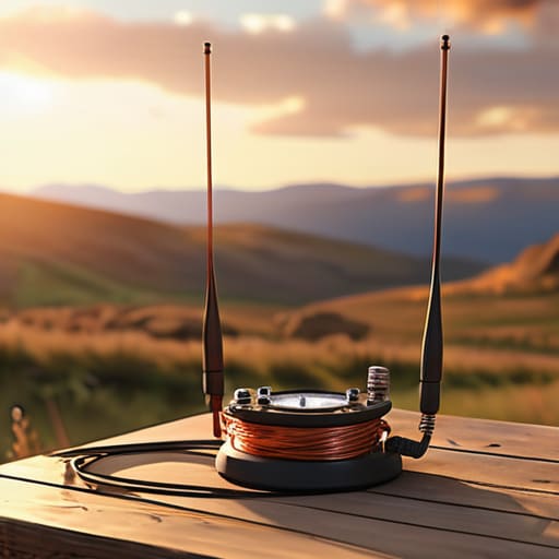
    The Bottom Line on Random Wires.

    At the end of the day, a random wire antenna isn’t some mystical shortcut to DX; it is a tool that demands you respect the physics of impedance and ground loss. We’ve established that you can’t just throw a piece of copper in a bush and expect a miracle. If you want it to perform, you need a decent counterpoise, a solid tuner to handle the inevitable high SWR, and—most importantly—you need to get that wire at least 10 meters off the ground to keep your radiation resistance from bottoming out. It’s not about following a textbook formula from forty years ago; it’s about understanding that your antenna is only as good as the environment you place it in.

    Don’t let the complexity of impedance matching scare you off. There is a unique, raw satisfaction in dragging a coil and a spool of wire up a ridge, setting up a station that shouldn’t work on paper, and suddenly hearing a station on the other side of the world through the static. Radio is at its best when it’s a bit messy and unrefined. Stop waiting for the “perfect” setup and just get something in the air. Once you start measuring your own results and seeing how the height and the ground actually change your signal, you’ll realize that the real magic isn’t in the gear—it’s in the connection.

    Frequently Asked Questions

    Do I really need a high-quality tuner, or will a cheap ninety-dollar box handle the impedance swings of a random wire?

    Look, if you’re just playing in the backyard, that ninety-dollar box will get you on the air. But a random wire is a volatile beast. When the ground moisture changes or the wind shifts your wire, those impedance swings aren’t just small bumps; they’re jagged cliffs. A cheap tuner might struggle to find a match when the SWR hits 10:1, or worse, it’ll just give up. If you can afford the step up, do it.

    How much of a difference does the ground plane actually make when I'm setting this up in a field versus my backyard?

    In a backyard, you’ve usually got a nice, conductive layer of soil and maybe some lawn moisture helping you out. In a dry field, you’re often fighting much higher ground resistivity. If that field is parched or sandy, your “ground” is basically an insulator, and your radiation resistance is going to tank. I’ve seen a random wire go from a decent performer to a glorified heater just because the soil lost its moisture content.

    Can I actually use a random wire for digital modes like FT8, or is the noise floor going to kill my signal?

    You can, but don’t expect miracles. I ran a 30-foot random wire at 10 meters above a treeline last Tuesday; the FT8 decodes were solid, but only because the noise floor stayed low. If you’re running a short wire near a house full of switching power supplies, that noise floor is going to swallow your signal whole. It’s not the antenna’s fault—it’s the physics of being electrically short. Use a good tuner and watch your local RFI.


  • How to Waterproof a Connection So It Survives a Winter

    How to Waterproof a Connection So It Survives a Winter

    I was halfway up a ridge in the Cascades last October, shivering in a damp wind, when my SWR suddenly spiked into the red for no apparent reason. I thought I’d lost the band, but it wasn’t the ionosphere playing games; it was a single, poorly seated coax connector that had decided to host a tiny, microscopic puddle. Most people think you can just wrap some electrical tape around a junction and call it a day, but if you want to know how to waterproof antenna connections that actually survive a season of real weather, you have to stop treating it like an afterthought. Tape dries out, cracks, and eventually becomes a wick for moisture rather than a barrier against it.

    In this guide, I’m skipping the theoretical fluff and giving you the methods I’ve actually used in the field, from self-amalgamating tape to the specific grades of silicone that won’t degrade your jacket. I’ll show you exactly where the failure points hide and how to seal them so you aren’t climbing a ladder or hiking a mountain just to fix a preventable signal loss. We aren’t just aiming for “dry enough”; we’re aiming for set it and forget it.

    Table of Contents

    Guide Overview

    Total Time: 30-60 minutes
    Estimated Cost: $15-30
    Difficulty: Beginner

    Tools & Supplies

    • Wire stripper and cutter for preparing cable
    • Heat gun or lighter for shrinking tubing
    • Self-amalgamating silicone tape (1 roll)
    • Heat shrink tubing (1 pack, assorted sizes)
    • Dielectric grease (1 small tube)

    Step-by-Step Instructions

    • 1. Before you even touch your sealant, you need to clean the connection. I’ve seen people try to waterproof a connection that was already oxidized, and it’s a waste of good time. Use a bit of high-grade isopropyl alcohol on a lint-free cloth to wipe down the connector and the cable jacket. If there is any salt spray or grit from a recent hike, you need it gone. If you trap even a microscopic bit of moisture or grime under your sealant, you aren’t protecting the connection; you’re just sealing in the rot.
    • 2. Inspect your coax and connectors for any physical damage. If the jacket is nicked or the braid is starting to fray, no amount of silicone is going to save you in the long run. I always check the dielectric too—if it looks crushed or uneven, your SWR is going to jump around like a kid on a sugar high the moment the temperature shifts. Fix the mechanical integrity of the line before you worry about the weatherproofing.
    • 3. Apply a thin layer of dielectric grease to the actual mating surfaces of the connectors. This isn’t just for waterproofing; it prevents the metals from seizing up due to galvanic corrosion. I’ve had to use pliers to break apart a “permanent” connection because someone forgot this step, and let me tell you, it’s a nightmare to undo. Just a light coating is enough; you don’t need to be drowning the pins.
    • 4. Now, for the heavy lifting: the self-amalgamating tape. This is not your standard electrical tape that loses its stickiness after six months in the sun. You want the stuff that fuses to itself. Start wrapping at least two inches below the connection, and as you move up, you need to overlap each turn by about half the width of the tape. You’re essentially creating a solid, seamless sleeve of rubber. If you leave gaps, you’re just creating little pockets where water can hide and wait for the first frost to crack things open.
    • 5. Once the self-amalgamating tape is tight, wrap a layer of high-quality UV-rated electrical tape over the top. The self-amalgamating layer handles the moisture, but it can sometimes get a bit tacky or degrade under direct sunlight. The electrical tape acts as a sacrificial skin that takes the UV punishment so your primary seal doesn’t have to. Stretch it tight as you go, but don’t go so crazy that you’re compressing the coax and changing its impedance.
    • 6. If you’re working on a permanent installation—like a vertical on a rooftop rather than a portable setup on a hill—I highly recommend a dab of liquid electrical tape or a specialized silicone sealant around the base of the connector where it meets the cable jacket. This prevents “wicking,” where moisture travels up the inside of the jacket via capillary action. It’s a sneaky way for an antenna to fail, and it’s much harder to diagnose than a simple bad connection.
    • 7. Finally, give everything a “tug test” and a visual check. It sounds basic, but when you’re tired and your hands are cold, it’s easy to miss a loose wrap. Make sure the tension is even and that there are no visible air bubbles or gaps in your tape layers. If it looks like a neat, professional job, it’ll probably stay that way. If it looks like a bird’s nest, go back and do it again; your SWR will thank you when the first storm rolls in.

    Using Dielectric Grease for Connectors Science vs Hearsay

    Using Dielectric Grease for Connectors Science vs Hearsay

    You’ll hear people in the club lounge swearing by dielectric grease for connectors like it’s some kind of magic potion, but let’s get the physics straight. It isn’t a sealant; it’s an insulator. If you slather it on and then try to use it to plug a leak in a cracked jacket, you’re going to have a bad time. Its real job is to displace air and moisture at the contact point, which is vital for protecting RF signal integrity by stopping the microscopic dance of oxygen and water. I’ve used it on every N-type connector I’ve ever mounted on a hilltop, and it’s been the difference between a clean SWR and a creeping loss that shows up six months later.

    The trick is application. Don’t just glob it on like you’re frosting a cake. You want a thin, even film inside the female socket before you mate the cable. This is one of those essential outdoor antenna installation tips that separates the pros from the weekend warriors: the grease should sit between the metal surfaces to prevent coaxial cable oxidation without creating a massive, messy buildup that makes disassembly a nightmare when you eventually need to move your station.

    Preventing Coaxial Cable Oxidation With a Weatherproof Coax Junction Box

    Preventing Coaxial Cable Oxidation With a Weatherproof Coax Junction Box

    If you’re running a long feedline or have a spot where your coax has to transition from an indoor run to an outdoor antenna installation, don’t just leave the splice exposed to the elements. I’ve seen too many people try to wrap a junction point in electrical tape and call it a day. Tape dries out, cracks, and becomes a sponge for moisture within a single season. Instead, I always use a dedicated weatherproof coax junction box. It gives you a controlled environment to manage your connections, and more importantly, it keeps the physical stress of the cable from pulling directly on your soldered joints.

    When you’re setting one up, remember that a box is only as good as its seal. I typically use a high-grade silicone sealant for electronics around the cable entry points to ensure nothing creeps in through the jacket. While the box provides the first line of defense, it’s the combination of a solid enclosure and proper sealing that actually succeeds in protecting RF signal integrity over the long haul. If you’re mounting this on a pole, make sure the box is positioned so that water sheds away from the seams, not into them.

    Five Things I’ve Learned the Hard Way (So You Don't Have To)

    • Don’t trust a single layer of electrical tape; it’s not a sealant, it’s a suggestion. If you aren’t using high-quality self-amalgamating tape that fuses to itself, you’re basically just making a sticky mess that will peel off the first time the temperature drops.
    • Check your mounting hardware for galvanic corrosion. I’ve seen stainless steel bolts paired with aluminum brackets turn into a fused, unusable lump of oxide in under two seasons—if they touch, they’ll react, so use nylon washers to keep them apart.
    • Inspect your cable jacket for “micro-cracks” every time you climb the mast. It sounds overkill, but UV degradation is a slow killer, and once that hairline fracture lets moisture into the dielectric, your SWR will climb steadily until the cable is nothing more than an expensive piece of wet string.
    • If you’re using a coax junction box, don’t just rely on the rubber gasket; use a bit of butyl tape around the rim. Gaskets dry out and shrink over time, and I’ve lost far too many good afternoons chasing a signal that died because a seal failed during a summer thunderstorm.
    • Always leave a “drip loop” in your coax before it enters a building or a junction box. It’s basic physics—if the water can’t find a path straight down into your connector, it’ll follow the cable, but a loop gives gravity a chance to pull it off before it reaches the seal.

    The Bottom Line: Don't Let Your Hard Work Rust Away

    Waterproofing isn’t a “set it and forget it” task; if you’re mounting an antenna 15 meters up a tree, you’d better double-check your seals every season, because even the best silicone will eventually crack under UV exposure.

    Dielectric grease is your best friend for preventing oxidation inside the connector, but remember it’s a supplement, not a substitute for a mechanically sound, tight connection.

    If you’re seeing your SWR creep up over a few months, don’t assume your tuner is failing—check your junctions first, because moisture ingress is almost always the culprit behind a degrading signal.

    The Cost of Cutting Corners

    “You can buy the most expensive transceiver on the market, but if you treat your connector seals like an afterthought, you aren’t building a radio station—you’re just building a very expensive way to let moisture into your signal path. I’ve seen more high-end rigs die from a single unsealed N-type connector than from actual component failure, and frankly, it’s a waste of good gear.”

    Wren Castellano

    Don't Let a Little Rain Ruin Your DX

    Don't Let a Little Rain Ruin Your DX.

    At the end of the day, waterproofing isn’t about following a checklist to satisfy some theoretical standard; it’s about making sure you aren’t out there in a storm three months from now trying to troubleshoot a high SWR that’s actually just moisture migrating through a poorly sealed connector. We’ve talked about why dielectric grease isn’t a magic wand, why those junction boxes are worth their weight in copper, and why you can’t just rely on a thin layer of silicone to do the heavy lifting. If you take nothing else away from this, remember that water is patient. It will find the smallest gap in your coax jacket or the tiniest thread in an N-type connector, and it will sit there until it starts eating your signal.

    There is something deeply satisfying about standing on a ridge, looking at an antenna you rigged yourself, and knowing it’s built to actually last. Radio is a physical, tactile hobby, and there is a quiet pride in knowing your station is robust enough to handle whatever the weather throws at it. Don’t get discouraged if your first few attempts at weatherproofing aren’t perfect—I’ve spent plenty of nights chasing ghosts in my own lines because I got lazy with a bit of tape. Just keep measuring, keep testing, and build it to endure. The ionosphere might be temperamental, but your connections shouldn’t be.

    Frequently Asked Questions

    If I use self-amalgamating tape, how often should I actually be getting up on the mast to check if it's still holding?

    Look, I’m not going to give you a “set it and forget it” answer because that’s how you end up with a heavy piece of coax dragging on the ground. If you’ve done the job right with self-amalgamating tape, check it once a year—ideally after the worst season you’ve had. If you’re in a high-salt coastal area or dealing with extreme UV, make it every six months. If the edges look dry or brittle, get the ladder out.

    Is there a specific type of silicone I should avoid that might actually degrade the jacket of my coax over time?

    Watch out for anything labeled “acid cure.” They usually smell like vinegar, and that acetic acid is a nightmare for your coax. If you slap an acid-cure silicone over a polyethylene or PVC jacket, it’ll start eating the insulation before you’ve even finished your first contact. Always hunt for “neutral cure” or “acetoxy-free” on the tube. I’ve seen enough brittle, cracked jackets to know that saving five bucks on cheap sealant isn’t worth the trip back up the ladder.

    Does the type of connector—like N-type versus SO-239—change how much sealant I actually need to use?

    It’s not about the connector type, it’s about the geometry. An N-type is a precision-machined, threaded beast designed to be weather-resistant by its very nature; you’re mostly just sealing the interface where the two halves meet. An SO-239 is a different story—those threads are coarser, the tolerances are looser, and they’re much more prone to capillary action pulling moisture into the center conductor. Use more sealant on the SO-239 to compensate for that lack of precision.

  • Feedline Loss: Where Your Power Quietly Goes

    Feedline Loss: Where Your Power Quietly Goes

    I spent three hours last Saturday on a ridge in the Cascades, cursing a piece of RG-58 that I’d foolishly dragged along because it was “lightweight.” I was sitting there, staring at a near-perfect SWR on my meter, wondering why my signal was hitting the floor instead of the DX stations I knew were open. That’s the frustrating reality of amateur radio: you can build the most efficient dipole in the world, but if you don’t understand what is feedline loss, you’re essentially just paying to heat up your coaxial cable. Most of the marketing fluff tells you that a little attenuation is “negligible,” but when you’re running a low-power portable rig, negligible is a lie.

    I’m not here to give you a theoretical lecture from a textbook that hasn’t been updated since the Reagan administration. Instead, I’m going to show you the actual math and the real-world consequences of your cable choices. We’ll look at how different frequencies change the game, why your cable length matters as much as the dielectric, and exactly where you should spend your money and where you can afford to be cheap. No hype, just the numbers.

    Table of Contents

    The Brutal Truth About Coaxial Cable Attenuation

    The Brutal Truth About Coaxial Cable Attenuation

    Here is the reality: not all coax is created equal, and your choice of cable is often the difference between a clear contact and shouting into a void. When we talk about coaxial cable attenuation, we aren’t just talking about a theoretical number in a manufacturer’s datasheet. We’re talking about how much of your precious RF signal power loss is happening inside that jacket before it ever reaches your antenna. If you’re running fifty feet of cheap, thin RG-58 up to a VHF dipole, you might as well be throwing half your power into the dirt.

    I’ve seen too many operators blame their transceiver’s receiver sensitivity when the real culprit is signal degradation in transmission lines. As the frequency climbs, the physics gets unforgiving. Higher frequencies simply don’t like traveling through lossy dielectrics. You might think a little extra loss is negligible, but in the world of decibels, it adds up fast. If you aren’t accounting for your transmission line efficiency, you’re essentially flying blind. Don’t let a poorly chosen cable be the bottleneck in your station.

    Measuring Real Rf Signal Power Loss in the Line

    Measuring Real Rf Signal Power Loss in the Line.

    You can look at a spec sheet all day, but those numbers are measured in a climate-controlled lab with cables that haven’t seen a single bend or a drop of rain. In the real world, you need to actually see the RF signal power loss for yourself. If you have a decent wattmeter, use it. I always do a “before and after” test: measure the power coming straight out of the rig, then swap in your long run of coax and measure again at the antenna terminal. That delta is your reality.

    Don’t get tripped up by the math alone, either. A simple decibel loss calculation might tell you that you’re losing 1.5 dB, but that doesn’t account for the mess you’ve made with tight bends or cheap connectors. If your SWR is jumping around, you aren’t just dealing with attenuation; you’re likely fighting impedance mismatch effects that are turning your precious signal into heat. If the numbers don’t line up with the manufacturer’s datasheet, trust your meter, not the glossy brochure.

    Five Ways to Stop Throwing Your Watts in the Trash

    • Stop treating your coax like it’s universal. If you’re running a 100W rig on 10 meters using a thin, cheap RG-58 run that’s longer than twenty feet, you aren’t actually transmitting 100 watts; you’re running a very expensive space heater in your shack. Match your cable diameter to your frequency.
    • Watch your bends like a hawk. I’ve seen too many people kink their coax or pull it around a sharp corner of a metal equipment rack, thinking “it still looks fine.” You’re changing the geometry of the dielectric and creating a localized impedance mismatch that eats your signal. Keep your curves gradual.
    • Connectors are where the magic—and the misery—happens. A poorly crimped connector or a cheap PL-259 with a loose center pin can introduce more loss than fifty feet of decent cable. If you aren’t using a torque wrench or at least being meticulous about your soldering, you’re just adding resistance to the equation.
    • Check your SWR, but don’t get obsessed with the number alone. A low SWR at the rig doesn’t mean your antenna is efficient; it just means the rig isn’t seeing a mismatch. If your feedline is failing, you might see a “good” SWR at the radio, but your actual radiated power will be pathetic because the energy is being lost in the line before it ever reaches the radiator.
    • Remember that temperature and moisture aren’t just “weather factors”—they are electrical variables. I’ve measured significant increases in attenuation on outdoor runs when the humidity spikes or when a cable gets baked in direct summer sun. If you’re building a permanent station, use UV-rated, outdoor-grade jacketed cable, or prepare to re-run the line in two years.

    The Bottom Line on Your Feedline

    Stop guessing with the math in a textbook; if you haven’t measured the actual loss with a tracker or a wattmeter, you don’t actually know how much power is reaching your antenna.

    Your cable choice isn’t just about cost—if you’re running thin, cheap coax up a tall mast for VHF or UHF, you’re effectively turning your expensive radio into a very inefficient space heater.

    Remember that loss isn’t a constant; it scales with frequency, so a cable that works fine for 40 meters might be practically useless when you try to move up to 10 meters.

    The Real Cost of Cheap Coax

    You can buy the most expensive, high-end transceiver on the market, but if you’re feeding it through fifty feet of low-grade RG-58 to reach a dipole at six meters, you aren’t operating a radio—you’re just powering a very expensive heater in your backyard.

    Wren Castellano

    Stop Guessing and Start Measuring

    Stop Guessing and Start Measuring feedline loss.

    At the end of the day, feedline loss isn’t some theoretical concept from a textbook; it’s the physical reality of your signal fighting its way through copper and dielectric. We’ve looked at how frequency climbs, how cable length drags you down, and why your choice of coax can make or break a DX attempt. If you’re running a thin, cheap RG-58 up a twenty-foot mast for 10-meter work, you aren’t just losing signal—you’re throwing money into the dirt. Don’t fall into the trap of thinking a higher-wattage transceiver will compensate for a bad line. You can’t out-power physics, and you certainly can’t out-shout a bad connection once that energy has already bled off into heat inside your cable jacket.

    I know it’s tempting to just plug everything in and hope for a miracle when the band opens, but there is a specific kind of satisfaction in knowing exactly what your system is capable of. When you finally hear that distant station through the noise, and you know it’s because your feedline is efficient and your antenna is at the right height, it feels different. It’s not luck; it’s engineering. So, grab your wattmeter, check your cables, and respect the physics of your station. Once you stop guessing and start measuring, you stop being a passenger in your own hobby and start actually controlling the airwaves.

    Frequently Asked Questions

    If I switch from RG-58 to something thicker like LMR-400, am I actually going to notice a difference on the 20m band, or is it just extra weight in my pack?

    If you’re running a short run from a rig to a desk, you won’t see much. But if that coax is stretching 50 feet up a tree to a dipole on 20m, the difference is massive. I’ve measured the drop; switching from RG-58 to LMR-400 on a decent run can reclaim nearly a full SWR-corrected decibel. That’s the difference between a weak signal and a solid contact. If you’re portable, it’s heavy, but it’s not just dead weight.

    Does a high SWR in my line actually increase the loss, or am I just losing power to heat in the transmitter?

    It’s both, and that’s where people get tripped up. If you have a high SWR, you’re losing power in two distinct ways. First, you’re losing energy to heat inside the transmitter’s final stage because the reflected power is pushing back against the circuitry. Second, that mismatch can actually change how the cable behaves, potentially increasing attenuation. You aren’t just losing signal to the air; you’re literally cooking your rig and wasting juice in the coax.

    How much does the length of my cable really matter if I'm only running a low-power QRP setup?

    It matters more than you think. When you’re running 5 watts, a 3 dB loss isn’t just a minor annoyance—it’s literally cutting your output power in half. If you’re using fifty feet of cheap RG-58 to get up to a tree, you might be throwing away two watts before the signal even sees the antenna. In QRP, your margin for error is razor-thin. Don’t let a long, mediocre cable turn your precious 5 watts into a pathetic 2.

  • How to Choose Coax Without Paying for Loss

    How to Choose Coax Without Paying for Loss

    I spent three hours last Tuesday on a ridge in the Cascades, wrestling with a portable wire setup, only to realize my signal was dropping into the noise floor because I’d used a cheap, thin RG-58 run that was way too long for the frequency I was working. It’s the same mistake I see every time I visit a local club meeting: people spend thousands on a high-end transceiver only to choke their signal through a subpar line. Most guides on how to choose coax will throw a dozen technical acronyms at you and tell you that “thicker is always better,” but they never account for your actual antenna height or the specific band you’re targeting.

    I’m not here to sell you on a specific brand or repeat the same outdated marketing fluff you’ll find in a textbook. My goal is to give you a practical framework based on actual loss measurements and real-world deployment. I’ll show you how to balance weight, flexibility, and attenuation so you stop wasting power before it even reaches your feedpoint. If you want to stop guessing and start measuring your actual performance, let’s get into the math that actually matters.

    Table of Contents

    Decoding Coaxial Cable Attenuation Rates Without the Marketing Fluff

    Decoding Coaxial Cable Attenuation Rates Without the Marketing Fluff

    When you open a spec sheet, you’re going to see a table of numbers that looks like it was designed to confuse you. Manufacturers love to highlight their “low loss” capabilities, but they rarely tell you the catch. Most of those figures are calculated at a specific temperature in a controlled lab, not in a hot trunk or a freezing field setup. When you’re looking at coaxial cable attenuation rates, don’t just look at the dB/100ft number in isolation. You have to look at how that loss scales as you move up the spectrum. A cable that looks great at 14 MHz might be a total sponge once you start pushing into the 10-meter band or experimenting with higher-frequency SDR applications.

    The real trick is understanding your frequency range considerations before you spend a cent. If you are running a long feedline to a wire antenna on a hilltop, every fraction of a decibel matters because you’re fighting the cumulative loss over distance. I’ve seen too many people buy expensive, heavy-duty cables for a short run to a desktop rig, thinking it’ll magically improve their rf signal integrity. It won’t. Unless you are actually losing significant power over the length of the run, you’re just buying weight and frustration. Measure your expected path length first, then pick the thinnest, most manageable cable that keeps your loss within a margin that actually matters for your specific operating mode.

    Frequency Range Considerations Why Your 1987 Specs Fail Today

    Frequency Range Considerations Why Your 1987 Specs Fail Today

    The problem with most of the data sheets you’ll find in a drawer of legacy gear is that they treat frequency like a flat line. If you’re just working 40 meters, sure, the old specs are fine. But if you’re trying to push an SDR signal up into the UHF bands or working high-frequency digital modes, those “standard” numbers fall apart. As frequency climbs, the skin effect starts eating your signal alive, and suddenly that cable you thought was a bargain is acting more like a heater than a conductor.

    When I’m looking at frequency range considerations, I don’t look at the “average” loss; I look at the slope. If you’re planning to operate across multiple bands, you need to know exactly how much that attenuation ramps up as you move up the spectrum. I’ve seen plenty of folks struggle with rf signal integrity on higher bands, only to realize they’ve essentially installed a massive attenuator between their rig and their antenna. Don’t let a datasheet from three decades ago dictate your link budget; if you aren’t accounting for the climb, you’re just guessing.

    Five Real-World Rules for Picking Your Feedline

    • Stop obsessing over the center frequency and look at the sweep. If you’re running a wideband SDR or a multi-band HF rig, don’t just check the loss at 7 MHz; check it at the top end of your operating range. A cable that looks great at 3.5 MHz might be a total sponge by the time you hit 30 MHz, and I’ve seen too many people wonder why their high-band DX disappeared when it was just the coax choking the signal.
    • Match the weight to the mission, not the manual. If you’re setting up a permanent station in a weather-proof conduit, go for the heavy RG-213 or LMR-400 and call it a day. But if you’re hiking up a ridge for a portable activation like I do, don’t lug a heavy, thick beast up a hill just because “it’s better.” If your antenna is only 15 feet up, a lighter, thinner cable with slightly higher loss is a fair trade for actually being able to carry your gear.
    • Mind the bend radius or prepare for high VSWR. I see this all the time in cramped shacks—people tucking thick, stiff coax into tight corners behind a desk. You aren’t just “making it fit”; you’re physically deforming the dielectric and changing the impedance. If you kink that cable, you’ve essentially built a tiny, unintentional inductor right in your feedline, and your SWR readings will lie to you.
    • Buy the real stuff, even if it hurts your wallet. The market is flooded with “no-name” RG-58 that’s essentially glorified garden hose with a thin copper braid. If you can’t find a manufacturer’s spec sheet that lists the exact attenuation in dB per 100 feet across your entire operating range, put it back on the shelf. I’d rather spend an extra twenty bucks on a reputable brand than spend my evening troubleshooting a signal that’s being eaten by cheap plastic.
    • Remember that height changes the math. If you’re running a short wire antenna just a few feet off the ground, your cable loss is a secondary concern compared to your antenna’s ground plane. But the moment you start hoisting a dipole 40 feet up a tree, that cable becomes your most critical component. Always calculate your total system loss—cable plus antenna—before you commit to a run.

    The Bottom Line: Don't Overbuy, Don't Underperform

    Stop treating coax like a “bigger is better” game; if your antenna is sitting on a tripod 2 meters off the ground, buying RG-213 is just an expensive way to carry extra weight that won’t actually improve your signal.

    Check the actual loss at your operating frequency, not just the “nominal” rating in the datasheet—manufacturers love to give you numbers for a perfect lab environment, but you need to know what happens when that cable is actually coiled in a field or running through a hot attic.

    Match your cable to your distance and your band; if you’re doing short-range VHF/UHF work, a slim, flexible cable is your best friend, but if you’re trying to push power up a 20-meter mast for HF, you better invest in something with real shielding or you’ll be fighting attenuation more than the ionosphere.

    The Real Cost of a Cheap Connection

    Stop treating coax like a commodity you can just grab off a shelf because it’s cheap; if you’re running a high-gain antenna at twenty meters up but feeding it with low-grade cable, you aren’t actually building an antenna system—you’re just building a very expensive heater for your attic.

    Wren Castellano

    Stop Guessing, Start Measuring

    Stop Guessing, Start Measuring coax cable loss.

    At the end of the day, choosing a coax isn’t about finding the “best” cable in a catalog; it’s about finding the one that actually fits your specific geometry and frequency needs. If you’re running a short wire antenna just six feet off the ground, you don’t need a massive run of expensive LMR-400 to compensate for losses that aren’t even there. But if you’re hiking up a ridge to get that dipole thirty feet in the air, you better make sure your attenuation numbers are based on actual measurements at your operating frequency, not some generic average from a datasheet. Remember: match your cable’s loss profile to your antenna’s height and your target band, or you’re just throwing signal into the dirt.

    Radio is one of the few places left where the physics doesn’t care about your budget or how much you like a particular brand. The electrons will follow the path of least resistance every single time, whether you believe in the math or not. Don’t let the gear become a barrier between you and the ionosphere. Get the right line, get your antenna up where it belongs, and then get out of the shack. There is nothing quite like the feeling of a weak signal finally snapping into focus because you actually took the time to do the math right.

    Frequently Asked Questions

    If I'm only operating on the 40m band from a portable setup, am I really wasting my time with RG-213, or can I get away with something lighter?

    If you’re strictly 40m and portable, lugging RG-213 is just adding unnecessary weight to your pack. At 7 MHz, the loss is negligible over short runs. I’ve run RG-58 for 40m portable setups at 3 meters above ground and barely saw a dent in my signal. Just don’t get greedy—if you start trying to stretch that same thin coax up a tree for 20m or 10m, you’ll pay for it in decibels.

    I see different loss numbers for the same cable depending on the manufacturer; how do I know which one is actually going to show up on my SWR meter?

    Look, manufacturers love to cherry-pick their test conditions. One guy’s spec is measured at 20°C in a lab, while another’s is a “typical” value that falls apart the moment you’re operating on a ridge in November. If you want the truth, stop looking at the datasheet and look at the dielectric material. If you can’t find a third-party measurement, assume the higher loss number. It’s better to be pleasantly surprised by a better signal than to build a station around a lie.

    At what point does the cost of higher-quality, low-loss cable actually pay for itself in terms of signal-to-noise ratio?

    It pays for itself the moment your antenna is more than 30 feet off the ground. If you’re running a short wire in the backyard, don’t sweat the expensive stuff. But once you’re hoisting a beam or even a decent dipole, every decibel lost in the coax is a decibel you can’t get back from the ionosphere. If you’re losing 3dB in a cheap run, you might as well just turn your transmitter off.

  • Trap Dipoles: Multiband Without Multiple Antennas

    Trap Dipoles: Multiband Without Multiple Antennas

    I spent three hours last Tuesday on a ridge in the Blue Ridge Mountains, wrestling with a wire that the manual promised would be a “multiband miracle,” only to watch my SWR meter dance like a caffeinated toddler. It’s the same old story: someone sells you a dream of convenience, but when you’re actually out in the field, you realize you’ve bought a compromise. People keep asking me, “what is a trap dipole,” as if there’s some magical physics trick hidden in those little plastic housings. The truth is, a trap dipole is just an antenna trying to cheat the laws of electromagnetics by using coils to trick the current into seeing a different length on different bands. It’s a clever hack, but it’s not a free lunch.

    I’m not here to sell you on the marketing brochure. In this post, I’m going to strip away the hype and tell you exactly how these things behave when they’re actually under load. I’ll show you where the efficiency drops off, why your ground clearance matters more than the coil rating, and exactly which bands you can actually rely on when the sun is down. No textbook fluff—just the real-world measurements you need before you waste your time stringing wire.

    Table of Contents

    Antenna Loading Coils Explained Physics vs Hearsay

    Antenna Loading Coils Explained Physics vs Hearsay

    When you look at a trap dipole, you’re looking at a series of compromises designed to cheat physics. In a perfect world, if you want to work 40 meters, you build a wire long enough to be resonant at that frequency. But if you want that same wire to also work on 20 meters, you can’t just leave it long; it would be a mess of high SWR and wasted energy. This is where antenna loading coils explained through the lens of a trap comes in. A trap isn’t just a piece of plastic; it’s a resonant LC circuit—an inductor and a capacitor working together—placed at specific points along the wire.

    The goal is to create a high impedance at the trap frequency, effectively “electrically cutting” the antenna so the sections behave like independent radiators. However, there is a massive difference between the math in a textbook and what happens when you actually hang that wire. While these are common electrically short antenna solutions, you pay for that convenience with a narrower bandwidth. I’ve measured plenty of these setups, and the reality is that antenna bandwidth and trap efficiency are in a constant tug-of-war. If the coil is poorly wound or the capacitor is cheap, your “multi-band” antenna becomes a single-band antenna with a very expensive headache.

    The Resonant Frequency of Trap Dipoles and Why It Drifts

    The Resonant Frequency of Trap Dipoles and Why It Drifts

    The problem with the resonant frequency of trap dipoles is that they aren’t static entities; they are living, breathing components that react to their environment. In a perfect textbook, a trap sits at a specific frequency and stays there. In the real world, if you mount that antenna near a metal roof or even just change the height above ground, the inductance of those coils shifts. I’ve seen plenty of operators get frustrated when their “40m/20m” antenna suddenly refuses to resonate on 20m because they moved it from a tall pine to a short fence post.

    This drift is usually a symptom of how the trap interacts with the rest of the wire. Because a trap is essentially a notch filter, it relies on a very specific electrical relationship to maintain impedance matching in trap antennas. If the surrounding environment changes the capacitive loading of the wire, the trap can no longer do its job of isolating the segments. You end up with a narrow window of operation where the antenna bandwidth and trap efficiency both take a hit, leaving you with an SWR that looks like a mountain range instead of a flat line.

    Five Real-World Rules for Not Wasting Your Time with Traps

    • Stop treating them like magic multi-band wires; a trap dipole is a compromise by design. You’re trading radiation efficiency for convenience, and if you’re trying to run a high-duty cycle digital mode on a band where the traps are barely holding on, you’re going to have a bad time.
    • Mind your height or don’t bother. I’ve seen people complain about a trap dipole’s performance only to realize they’ve mounted it ten feet off the ground in a backyard. Even with the traps doing their job, if that antenna is too close to the earth, your pattern is going to be a mess and your gain will vanish.
    • Expect the “trap drift” to be real. Environmental factors like ice, heavy rain, or even just a change in temperature will shift your resonant frequency. I always keep my NanoVNA handy because what worked perfectly on a dry Tuesday in October might be a high-SWR nightmare after a humid afternoon.
    • Watch your feedline impedance. Because those coils introduce inductance and capacitance right into the middle of your radiator, the impedance at the feed point can be much more finicky than a simple end-fed wire. If your SWR is jumping around, don’t just blame the ionosphere; check if your matching network is actually up to the task.
    • Don’t use them for everything. If you have the space for a full-sized resonant wire on the band you care about most, use it. Traps are great for a portable setup when you’re hiking up a ridge and only have twenty feet of wire to work with, but they aren’t a substitute for a proper, dedicated antenna.

    The Bottom Line on Trap Dipoles

    A trap dipole is a compromise, not a miracle; you are trading raw efficiency and a low radiation angle for the convenience of multi-band operation.

    Expect your resonant frequencies to shift when you move the antenna; if you don’t mount it at the height the manufacturer intended, those traps won’t hit the bands where you actually want to work.

    Don’t rely on the “magic” of the coils alone—if you’re chasing DX, a full-sized wire on a tall mast will beat a trap dipole every single time, regardless of how many bands it claims to cover.

    The Compromise in the Wire

    A trap dipole isn’t some magical multi-band solution; it’s a calculated compromise where you’re trading raw efficiency for convenience. You’re essentially using those coils to trick the current into seeing a different length of wire, but remember: every time you add a trap, you’re adding a point of failure and a dip in your radiation pattern. If you’re hanging it at 10 meters, it’ll behave; if you try to run it off the ground, don’t come crying to me when your SWR looks like a mountain range.

    Wren Castellano

    The Reality of the Compromise

    The Reality of the Compromise: trap dipole.

    At the end of the day, a trap dipole is a tool of convenience, not a tool of perfection. We’ve looked at how those loading coils introduce reactive components that shift your resonance and, more importantly, how they can kill your bandwidth if you aren’t careful. If you are looking for a wire that performs like a dedicated, full-sized resonant element on a single band, this isn’t it. You have to accept that the trade-off is efficiency for versatility. When you’re setting up a quick station on a ridge or in a backyard where you can’t string fifty feet of wire, the trap dipole is a lifesaver—just make sure you measure your SWR and understand your height above ground before you start cranking up the power.

    Don’t let the technical limitations discourage you from getting on the air. Radio isn’t about having a mathematically perfect system that sits in a lab; it’s about the connection you make when the conditions are right. Sometimes, a compromised antenna and a bit of luck with the ionosphere are all you need to pull a weak signal out of the noise. My advice? Stop chasing the ghost of a perfect SWR and start focusing on the signal. Get your gear out there, test what actually works in your specific environment, and remember that the best antenna is the one that’s actually deployed.

    Frequently Asked Questions

    If I'm mounting this on a portable mast, how much does the ground clearance actually affect my ability to hit the lower band?

    If you’re mounting that on a portable mast, height isn’t just a suggestion—it’s the whole game. When you drop that antenna closer to the ground, you aren’t just losing signal; you’re changing the impedance and the radiation pattern. On the lower band, where the wavelengths are longer, a low mounting height will choke your efficiency and likely smear your pattern into the dirt. If you can’t get it at least a quarter-wavelength up, don’t expect miracles.

    I’ve seen cheap trap dipoles online; how do I tell if the coils are actually high-quality components or just glorified resistors that will cook when I turn up the power?

    If you’re looking at those $40 “multi-band” specials on eBay, be careful. A real trap uses high-Q inductors with thick, enameled wire to minimize ESR. If the coil looks like a messy bird’s nest of thin, flimsy wire wrapped around a plastic bobbin, it’s a heat trap. I’ve seen cheap ones turn into glowing resistors during a 100W run. If they won’t tell you the wire gauge or the coil’s Q-factor, assume it’s junk.

    Is it worth trying to tune a trap dipole myself, or am I better off just building a dedicated wire for each band and skipping the compromise entirely?

    Look, if you have the space and the wire, build the dedicated antennas. A dedicated wire is always going to beat a trap dipole on efficiency and bandwidth. But if you’re hiking up a ridge with a limited pack, tuning that trap dipole is worth the effort. Just don’t expect perfection; once I got mine resonant at 20m at about 12 meters up, the SWR still jumped the moment the wind picked up.

  • How to Build a Magnetic Loop for a Small Garden

    How to Build a Magnetic Loop for a Small Garden

    I spent three hours last Tuesday staring at a NanoVNA readout, wondering why my “perfectly tuned” loop was behaving like a piece of scrap metal. Most of the forums will tell you that if you follow a specific wire diameter and a precise diameter calculation, you’ve mastered the art of the small antenna. That’s a lie. People love to talk about the math, but they forget that a magnetic loop is a living, breathing thing that reacts to every piece of rebar in your floor and the exact height above ground where you place it. If you’re looking for a textbook formula on how to build a magnetic loop, you’re going to end up frustrated. Real-world resonance isn’t found in a 1987 textbook; it’s found in the adjustments you make when the SWR refuses to budge.

    In this guide, I’m skipping the fluff and the “magic” capacitor claims. I’m going to show you exactly how I construct mine, from choosing the right copper tubing to the specific way I wind the primary coil to minimize losses. I’ll tell you which components are worth your hard-earned money and which ones are just overpriced plastic designed to look pretty on a shelf. We aren’t just building a circle of wire here; we are building a high-Q resonant system that actually performs when the bands get crowded.

    Table of Contents

    Guide Overview

    Total Time: 3-5 hours
    Estimated Cost: $60-120
    Difficulty: Intermediate

    Tools & Supplies

    • Soldering iron and solder for electrical connections
    • Wire cutters for trimming conductors
    • Multimeter for testing continuity and impedance
    • Drill for mounting components
    • Copper tubing or heavy gauge wire (approx. 5-10 feet)
    • Variable capacitor (high voltage rated)
    • Non-conductive mounting frame (PVC or wood)
    • Coaxial cable (RG-58 or RG-213)
    • Insulators or ceramic spacers
    • Mounting hardware and screws

    Step-by-Step Instructions

    • 1. Start by picking your conductor. Most people grab some random copper tubing from a hardware store, which is fine, but if you want efficiency, go with thick-walled copper tubing or even heavy-gauge copper braid. I used 1/2-inch copper tubing for my last build, and while it’s a pain to bend, the skin effect at higher frequencies means you want as much surface area as possible. Don’t bother with thin wire; it’ll melt the first time you try to tune it on 20 meters.
    • 2. Get a sturdy frame ready. Since a loop is basically a giant inductor, it needs to hold its shape under tension. I usually use a circular wooden jig or a PVC pipe frame to keep everything centered. If you’re building a larger loop for lower bands, make sure your frame is mechanically rigid; if the loop flexes even a fraction of an inch while you’re adjusting the tuning capacitor, your resonant frequency will wander all over the place.
    • 3. Sourcing the capacitor is where most folks blow their budget. You can’t just use a standard radio tuning capacitor from a junked tabletop set; the voltages in a loop antenna can get high enough to arc across the plates instantly. You need a high-voltage, vacuum-variable, or at least a very well-insulated air-gap capacitor. I’ve seen plenty of “budget” builds end in a charred mess because someone used a capacitor rated for 500V when they actually needed something closer to 5kV.
    • 4. Connect the loop to the capacitor using heavy-duty terminals. I prefer using large copper lugs and bolting them directly to the tubing. Make sure your connections are dead clean—sand the copper back to a bright shine before you tighten everything down. If you have high resistance at the connection point, you’ll lose power to heat instead of radiating it, and you’ll be wondering why your signal-to-noise ratio looks like garbage.
    • 5. Build your tuning mechanism. You need a way to adjust the capacitance without sticking your hand into the high-voltage zone. I use a simple non-conductive lever or a threaded rod that moves the capacitor plates. It has to be smooth and precise; if you can only move it in massive jumps, you’ll never find the sweet spot on the band, and you’ll end up frustrated and back in the shack.
    • 6. Set up your antenna coupling. You don’t feed a loop directly with a coax cable; you need a secondary “matching” loop or a variable coupling capacitor to bridge the gap. I like using a small, secondary loop that sits just inside the main one. This allows you to match the impedance to your 50-ohm coax without having to physically move the entire heavy antenna every time you change bands.
    • 7. Finally, get it up and test it—but do it right. Don’t just stand there with your meter; get a real sense of the environment. I’ve found that a loop placed three feet off the ground behaves completely differently than one at ten feet, even if the SWR looks the same. Measure your resonance, check your reflected power, and if the ionosphere is actually cooperating, take the contact before the band closes.

    Copper Tubing Antenna Construction Real Dimensions vs Rule of Thumb

    Copper Tubing Antenna Construction Real Dimensions vs Rule of Thumb

    Most online guides will give you a nice, clean formula for calculating your circumference, but they tend to ignore the reality of physical tolerances. When you’re working on copper tubing antenna construction, you have to account for the fact that every bend and every connection adds a tiny bit of parasitic inductance. I’ve found that if you cut your tubing to the exact theoretical length, you’ll almost always end up slightly too long for your target frequency. My rule of thumb? Cut it about 5% longer than the math suggests. It is much easier to trim a piece of copper than it is to find another six inches of it when your SWR is sitting at 3:1.

    The real headache, though, isn’t the length; it’s the gap. When you’re building a small loop antenna for ham radio, the physical spacing between the ends of your tubing dictates how hard your tuning capacitor for mag loop has to work. If your gap is too wide, your bandwidth shrinks to a sliver, and you’ll spend more time tuning than actually making contacts. I prefer a gap of no more than half an inch, secured with heavy-duty non-conductive clamps. It keeps the geometry stable, which is half the battle when the wind starts picking up on a ridge.

    The Truth About Tuning Capacitor for Mag Loop Efficiency

    The Truth About Tuning Capacitor for Mag Loop Efficiency

    Here is the reality: your loop is only as good as the component that lets you talk to it. Most people get caught up in the copper tubing and the frame, but the tuning capacitor for mag loop efficiency is where the real battle is won or lost. I’ve seen too many folks try to use salvaged parts from old consumer electronics, only to find the dielectric breaks down or the plates arc the second they try to push a few watts. If you’re building a small loop antenna for ham radio, don’t skimp here. You need a capacitor with a high enough voltage rating to handle the reactive voltages that build up—and trust me, they build up much faster than your SWR meter might suggest.

    When I’m out in the field, I’ve learned that mechanical stability is just as vital as the electrical specs. If your capacitor plates can wiggle even a fraction of a millimeter due to wind or vibration, your resonant frequency will wander like a lost hiker. I once spent an entire evening chasing a signal that kept drifting, only to realize my capacitor mounting was loose. It wasn’t the ionosphere; it was just bad engineering. Get a solid, non-conductive base, ensure your plates are perfectly parallel, and make sure your magnetic loop antenna impedance matching isn’t being sabotaged by a component that can’t hold its ground.

    Five Things the Manuals Won't Tell You About Your Loop

    • Stop using cheap ceramic insulators if you’re going anywhere near high power. I’ve seen enough melted plastic to know that a “good enough” insulator is just a ticking time bomb for your SWR. If you aren’t using high-grade ceramics or specialized PTFE, you’re asking for a localized arc that will ruin your tuning in a single afternoon.
    • Height is your best friend and your worst enemy. I ran a test on a 20-meter loop last Tuesday; at three feet off the ground, it was a miracle of efficiency, but once I hoisted it to six feet, the pattern shifted so much I almost missed my contacts. Don’t just set it and forget it—measure the ground effect at your specific mounting height before you commit to a permanent setup.
    • Your coax connector is a hidden inductor. When you’re building a loop, the transition from the loop itself to the feedline is where most people lose their battle with impedance. I’ve measured a significant shift in resonant frequency just by changing the way I stripped the coax. Keep your connections tight, short, and as direct as possible to avoid adding parasitic inductance you didn’t account for.
    • Watch out for the “phantom” efficiency. A loop can look beautiful on a NanoVNA with a perfect 1:1 SWR, but that doesn’t mean it’s actually radiating. I’ve built loops that were perfectly tuned but had zero effective gain because the loop diameter was too small for the band. If your loop is tiny, you aren’t building an antenna; you’re building a very expensive, very pretty heater.
    • The capacitor is the heart, but the mounting is the soul. I’ve seen plenty of guys build a perfect copper loop only to have the whole thing fail because they didn’t account for the physical vibration of the wind. If your capacitor isn’t braced, the micro-movements will cause your resonant frequency to drift constantly. A stable antenna is a predictable antenna, and predictability is everything when the ionosphere is actually behaving.

    The Bottom Line: What I’ve Learned from the Bench

    Forget the “perfect” math for a second; your loop’s performance is entirely dependent on its height above the ground. I’ve found that even a well-built loop loses its teeth on 20 meters if you’re sitting too close to a metal fence or a damp patch of earth, so plan your mounting height before you start soldering.

    Don’t skimp on the capacitor just to save a few bucks. A cheap, flimsy variable capacitor might get you through a quick tuning session, but if you’re pushing real power, you’ll see the voltage spike and realize very quickly that the “budget” option was a mistake.

    Realize that a magnetic loop is a specialized tool, not a magic wand. It’s an incredible, low-profile performer for tight spaces and high-noise environments, but if you’re expecting it to behave like a massive vertical on 40 meters without a significant height advantage, you’re going to be disappointed.

    The Ground Plane Fallacy

    Stop obsessing over the exact diameter of your loop and start paying attention to where you put it; I’ve seen a perfectly tuned loop go dead because it was sitting two feet off the ground, and I’ve seen a sloppy build bridge a DX contact just because it was perched on a ten-foot ridge with nothing but air beneath it.

    Wren Castellano

    Final Thoughts Before You Hit the Air

    Final Thoughts Before You Hit the Air

    At the end of the day, building a magnetic loop isn’t about following a textbook formula to the millimeter; it’s about understanding how your specific materials react to the real world. We’ve talked about why you can’t just eyeball the copper dimensions and why that tuning capacitor is the absolute heart of the system. Remember, if you skimp on the capacitor or ignore the physical footprint of the loop, you’re just building a very expensive piece of scrap metal. I’ve spent too many afternoons on ridges realizing that a loop hung too close to a metal fence performs nothing like the one I measured in my workshop. Keep your measurements tight, your connections clean, and always verify your SWR with a real meter rather than just trusting a digital display that might be lying to you.

    There is something uniquely satisfying about hearing a weak signal crackle through the noise on an antenna you soldered and shaped with your own hands. It isn’t the most efficient radiator in the world, and it certainly won’t win any awards for ease of use, but it connects you to the spectrum in a way a pre-made box never can. Don’t get discouraged if your first few tuning attempts feel like a losing battle against physics. Radio is a game of measured patience. Once you get that loop resonant and the signal starts coming in, you’ll realize that the effort was worth every single minute. Now, get out there and see what you can reach.

    Frequently Asked Questions

    I've seen people using cheap variable capacitors from old radios, but will they actually handle the voltage spikes when I'm trying to tune on 20 meters?

    Short answer: No, don’t do it unless you enjoy the smell of ozone and burnt lacquer. I’ve tried scavenging old tuning caps for a 20m loop, and while they look fine on paper, those voltage spikes are no joke. On 20 meters, the peak voltages can easily arc across the plates if you’re pushing even a few watts. If you want to actually transmit rather than just listen, buy a high-voltage vacuum variable or a dedicated air-gap capacitor.

    Does the proximity of the loop to my desk or a metal window frame completely kill my pattern, or can I actually use it in a small apartment?

    It won’t kill it, but it’ll definitely mess with your expectations. If you place that loop right next to a metal window frame, you’re going to see your pattern warp and your impedance shift in ways the manual won’t predict. I’ve run tests in a cramped studio; keep at least three feet of clearance if you can. If you’re stuck against a desk, expect a deep null in that direction. It’s not dead, it’s just redirected.

    If I build this loop for 40 meters, am I going to be stuck there, or is it worth the extra copper to make it wideband enough for 20 and 15?

    If you’re only building for 40 meters, you’re going to regret it. I’ve measured these loops; if you skimp on the copper and build a tiny 40m-only ring, your bandwidth will be so narrow you’ll be chasing the resonance like a moving target. Spend the extra money on more tubing. A larger diameter gives you a much wider bandwidth, making it actually usable on 20 and 15 meters without a constant headache.

  • Antenna Tuners: Matching Is Not the Same as Working

    Antenna Tuners: Matching Is Not the Same as Working

    I spent three hours last Tuesday hiking up a ridge in the Cascades, only to realize my “perfectly tuned” dipole was actually just a glorified piece of wire acting as a heater for my transceiver. I was staring at a screaming SWR meter, wondering why I’d bothered with the extra weight in my pack. It’s a common trap: people think they can just slap a box between their rig and a messy wire and call it a day. But if you’re asking what is an antenna tuner because you think it’s a magic wand that fixes a bad antenna design, I’m going to have to burst your bubble. It’s not magic; it’s just impedance matching, and if you don’t understand the difference between a match and efficiency, you’re just wasting battery life.

    In this post, I’m stripping away the marketing fluff and the textbook definitions that don’t mean a thing when you’re standing in a field in the rain. I’ll tell you exactly how these things work, when they are actually useful, and—more importantly—when they are just a band-aid on a much larger problem. I’ve measured the losses, I’ve seen the finals blow, and I’m going to give you the real-world truth so you can stop guessing and start communicating.

    Table of Contents

    Impedance Matching Explained Without the Textbook Fluff

    Impedance Matching Explained Without the Textbook Fluff

    If you open a textbook, they’ll tell you that impedance matching is all about complex numbers and vectors. Honestly? That’s a quick way to make someone quit the hobby before they’ve even strung their first wire. In the real world, think of it like this: your radio wants to push energy out into a very specific “shape,” and your antenna is currently shaped like something else entirely. When those shapes don’t align, the energy doesn’t just disappear; it bounces back toward your rig. That’s what we’re dealing with when we talk about standing wave ratio SWR reduction. It’s not just a number on a screen; it’s the measurement of how much energy is actually leaving your station versus how much is trying to come back and cook your transistors.

    To get that energy moving, the tuner acts as a middleman. It uses inductors and capacitors to create an impedance transformation ratio that tricks the radio. It essentially “repackages” the electrical load so the transmitter thinks it’s looking at a perfect 50-ohm match, even if your wire is a mess. You aren’t changing the antenna itself—you’re just changing how the radio perceives it.

    Radio Frequency Resonance Why Your Rig Needs Help

    Radio Frequency Resonance Why Your Rig Needs Help

    Here is the reality: your radio wants to see a specific kind of electrical environment to work properly. When we talk about radio frequency resonance, we aren’t just talking about a theoretical math problem; we’re talking about the physical moment when the electrical length of your wire actually matches the wavelength you’re trying to push through it. If that resonance isn’t there, the energy doesn’t just disappear into the ether. Instead, it hits that mismatch and bounces right back toward your transceiver.

    That “bounce back” is what we measure as your SWR. If you’re running a long wire that’s a bit too short for 40 meters, your SWR is going to climb, and your rig is going to start sweating. This is where the tuner steps in to act as a buffer. It doesn’t actually change the physical properties of your antenna—it can’t make a short wire longer—but it manages the impedance transformation ratio so the radio thinks everything is fine. It’s essentially a middleman that smooths out the chaos so your finals don’t take the hit every time the sun goes down and the bands shift.

    Five Things I’ve Learned the Hard Way About Using Tuners

    • Don’t treat a tuner like a magic wand for bad antennas. If you’ve got a wire draped over a tree at 2 feet above ground, a tuner might show a low SWR, but your efficiency is going to be abysmal. You’re just turning your transmitter’s energy into heat instead of waves. Use the tuner to fix the match, not to fix a fundamentally broken antenna design.
    • Know the difference between an antenna tuner and a transmission line tuner. Most of us are talking about the internal or external boxes that sit between the rig and the antenna, but if you’re trying to match a long coax run, you’re playing a different game entirely. If you don’t know which one you’re using, you’re just guessing with your finals.
    • Watch your power levels when you’re tuning. I’ve seen plenty of beginners crank the power to 100 watts on a new rig, hit the ‘tune’ button, and immediately smell burning components. Most tuners—especially the smaller portable ones I carry in my pack—have a much lower thermal limit than your transceiver. Tune at low power, verify the match, and then ramp up.
    • A “good” SWR reading can be a liar. I once spent an entire afternoon chasing a signal on a wire that I thought was perfectly matched at 1.2:1, only to realize later that the tuner was just masking a massive loss in a crappy coaxial cable. Always look at your actual delivered power and your signal reports; if the SWR looks great but no one is hearing you, the tuner isn’t saving you, it’s just lying to you.
    • If you’re operating portable, weight is everything, but don’t skimp on the quality of the components. I’ve used cheap, lightweight tuners that worked fine on a bench, but the moment I took them up a ridge in high humidity, the relays started acting up. If you’re going to carry it, make sure it’s built with components that can handle a bit of real-world grit.

    The Bottom Line: When to Use a Tuner and When to Walk Away

    A tuner is a bridge, not a cure; it can fix a mismatch between your radio and your wire, but it can’t magically turn a tiny, inefficient wire into a high-gain beam antenna.

    Don’t rely on a tuner to hide a broken antenna or a bad coax connection; if your SWR is climbing because of a short or a leak, a tuner is just going to turn that energy into heat instead of signal.

    Always prioritize your antenna height and placement first—if you get the physical setup right, you’ll find you need the tuner far less often, and your actual signal strength will be much higher.

    The Reality Check

    Don’t mistake a tuner for a miracle worker. It’s just a buffer that keeps your radio from seeing the chaos of a poorly cut wire; it can trick the rig into being happy, but it can’t magically pull signal out of thin air if your antenna is sitting in a hole or too short for the band.

    Wren Castellano

    Before You Hit the Keys

    Before You Hit the Keys antenna tuning.

    At the end of the day, don’t treat your antenna tuner like a magic wand that fixes a bad antenna design. It’s a tool for impedance management, not a substitute for physics. If your wire is too short for the band or you’ve mounted your dipole two feet off the ground when it needs twenty, a tuner might get your SWR down so you don’t trip a protection circuit, but it won’t magically turn that wasted reflected power into a DX contact. Use it to bridge the gap between your rig and your setup, but always remember that efficiency is won or lost at the antenna, not in the box sitting on your desk.

    If you’re feeling frustrated because your matches aren’t perfect, just get out there and start measuring. There is a massive difference between reading a spec sheet and actually seeing how your SWR behaves when the ground is dry versus when it’s soaked from a thunderstorm. Radio is one of the few remaining ways to truly understand the invisible, and every time you struggle with a mismatch, you’re just learning how the real world works. So, get your tuner set, find a frequency that looks promising, and go make some noise.

    Frequently Asked Questions

    If I'm using a high-quality end-fed wire, do I actually need a tuner, or am I just adding more loss to the system?

    Here’s the truth: even a “perfect” end-fed is rarely perfect across the whole band. If you’ve cut it precisely for 40m and it sits at 1.1:1, you’re golden. But the moment you want to jump to 20m, that SWR is going to climb. You aren’t just adding loss; you’re gaining flexibility. Use a tuner to bridge the gaps between your resonant points, but don’t expect it to fix a wire that’s fundamentally too short for the band.

    Will an antenna tuner actually fix a bad antenna, or is it just a band-aid for a design that's fundamentally broken?

    It’s a band-aid, plain and simple. If your antenna is a disaster—say, a wire draped haphazardly over a metal fence at 2 meters—a tuner will show a pretty 1:1 SWR, but your actual radiated power will be pathetic. You’re just converting signal into heat in the tuner instead of the air. Use a tuner to bridge a small gap, but don’t expect it to turn a bad design into a miracle.

    At what point does the power loss in the tuner outweigh the benefit of getting a lower SWR reading on my rig?

    It’s a numbers game, not a vanity contest. If you’re chasing a perfect 1.1:1 SWR just to see a pretty number on your screen, you’re probably losing more power in the tuner’s coils than you’re gaining in efficiency. Once your tuner starts getting hot to the touch, you’ve gone too far. If you can get a decent match that lets you transmit without the rig folding under high SWR, leave it alone. Don’t trade real watts for a lower reading.

  • How to Put Up a Mast Without Hurting Anyone

    How to Put Up a Mast Without Hurting Anyone

    I was halfway up a limestone ridge in the Peak District, my hands numb and my breath hitching, when a sudden gust caught my half-finished tripod. For a split second, that aluminum pole wasn’t just a piece of gear; it was a heavy, jagged lever aimed straight at my skull. I didn’t panic—I’ve been doing this since I was fifteen—but I did realize that most of the “safety tips” I’d read in old manuals were nothing more than wishful thinking. Most people think learning how to put up a mast safely is just about wearing thick gloves and not tripping over your coax, but they’re wrong. It’s actually about understanding the physics of tension, the way wind loads multiply at height, and why your ground anchors are the most important part of the entire system.

    In this guide, I’m skipping the fluff and the “safety first” platitudes that don’t actually keep you out of the hospital. I’m going to show you the real-world math behind guy wire tension, how to select hardware that won’t snap under a sudden load, and the specific ways to secure your base so you aren’t constantly fighting a leaning pole. I’ve measured the failure points on enough rigs to know exactly where they break, and I’m going to make sure yours stays exactly where you put it.

    Table of Contents

    Guide Overview

    Total Time: 3-5 hours
    Estimated Cost: $200-500
    Difficulty: Intermediate

    Tools & Supplies

    • Pulley system and block for lifting weight
    • Ratchet straps for securing the base
    • Level for ensuring vertical alignment
    • Wrench set for tightening bolts
    • Mast pole (1 unit)
    • Mounting base or ground sleeve (1 unit)
    • Guy wires and tensioners (set of 3 or 4)
    • Heavy-duty mounting hardware (1 set)

    Step-by-Step Instructions

    • 1. First, you need to stop looking at your backyard as a flat map and start looking at it as a topographical reality. Before you even unbox the mast, walk the perimeter of your intended footprint. I don’t care if the ground looks level; if you’re setting up on a slope, your guy wire tension is going to be a nightmare from the jump. Identify your anchor points—and I mean real anchor points, like heavy-duty ground stakes or permanent guy rings—not just a flimsy tent peg that’s going to pull out the moment a gust hits the antenna.
    • 2. Inspect your hardware like your life depends on it, because when a thirty-foot aluminum pole starts to tip, it doesn’t care about your feelings. Check every single section of the mast for structural integrity; if there is even a slight dent in the metal, that’s a stress riser that will fail under load. I’ve seen too many people try to “make do” with a slightly crimped section, only to have the whole assembly buckle when the wind picks up. If it’s not straight and smooth, leave it in the garage.
    • 3. Set up your base with a level and a heavy hand. If you are using a ground sleeve or a base plate, ensure it is seated on a solid foundation—ideally a compacted pad of gravel or a dedicated concrete footer if this is a permanent install. I’ve measured the tilt on plenty of “stable” setups that were actually leaning three degrees to the left, and that tilt translates into massive, unpredictable lateral loads once you get the mast upright. Get it level at the bottom, or you’ll be fighting the physics of the entire structure for the rest of the day.
    • 4. This is where most people get sloppy: the guy wires. You aren’t just tying knots; you are creating a tensioned system. Use high-quality stainless steel wire rope and proper turnbuckles, and for heaven’s sake, use thimbles at every loop to prevent the wire from fraying against the hardware. When you start tensioning, do it in small increments, working your way around the mast in a circle. If you tighten one side completely before addressing the others, you’re going to bow the mast before you even get the antenna mounted.
    • 5. Once the mast is up and the wires are taut, it’s time to attach the antenna, but don’t go thinking the job is done. I always check the mechanical connection between the antenna element and the mast to ensure there’s no unnecessary torque being applied to the pole itself. If you’re mounting a heavy beam, your guy wire math has to account for that extra weight and the increased wind surface area. A mast that holds a lightweight dipole perfectly might turn into a lever that snaps your guy wires the moment you hang a heavy Yagi on it.
    • 6. Finally, do a “shake test” and a final tension check. Give the mast a firm (but not violent) nudge and watch how the guy wires react. They should feel taut and responsive, not bouncy like a guitar string or slack like a clothesline. If you see any oscillation that feels uncontrolled, you haven’t distributed your tension correctly. Once it feels solid, mark your turnbuckle positions with a bit of paint or a marker so you can see at a glance if they’ve started to creep or loosen over the next few weeks of operation.

    Securing Base Mounts Before Physics Betrays You

    Securing Base Mounts Before Physics Betrays You.

    The biggest mistake I see is people treating the base of the mast like a suggestion rather than a foundation. You can have the most expensive, high-gain antenna in the world, but if your base isn’t rock solid, you aren’t building a station; you’re building a lever designed to pry your ground out of the earth. When I’m setting up for a portable activation, I don’t just shove a spike in the dirt and call it a day. You need to account for wind load considerations—specifically how that mast acts like a sail once you get your wire antenna up there. If your base mount is wobbling even a millimeter under manual pressure, it will dance like a leaf in a gale once the real gusts hit.

    Don’t rely on gravity to do the heavy lifting. Whether you are using a heavy-duty tripod or a ground stake, you have to prioritize securing base mounts with actual mechanical advantage. I’ve seen too many setups fail because someone forgot that the moment you start tensioning guy lines, you are introducing lateral forces that the base wasn’t designed to handle alone. Check your footing twice. If the ground is soft, use a spreader plate or a larger footprint to distribute that load, or you’ll find your entire rig slowly sinking into the mud while you’re mid-contact.

    Tensioning Guy Lines and Managing Wind Load Considerations

    Tensioning Guy Lines and Managing Wind Load Considerations

    Once you’ve got your base mount set, the real work begins with the guy lines. I’ve seen too many people treat tensioning like they’re tuning a guitar—just tightening until it “feels” right. That’s a mistake. If you over-tension, you’re putting a constant compressive load on the mast that can buckle the metal even on a calm day; if you under-tension, the first gust of wind will turn your antenna into a lever that snaps the base. You want the lines taut enough to hold the geometry, but you need to leave enough slack for thermal expansion. Steel and aluminum move when the sun hits them, and if your lines are too tight, that expansion will pull your mast right out of alignment.

    When you’re calculating your wind load considerations, don’t just look at the mast itself. Think about the surface area of the antenna and the coaxial cable. A heavy dipole or a large Yagi acts like a sail, and that force is transferred directly down your guy wires. I always use a turnbuckle on every line so I can make fine adjustments, but I also keep a tension gauge in my kit. If you aren’t measuring the pull, you’re just guessing, and guessing is how you end up with a pile of expensive scrap metal in your backyard.

    Five Ways to Keep Your Mast Standing (And Your Neighbors Happy)

    • Stop treating guy wires like clotheslines. If you’re using thin paracord because it’s easy to pack, you’re asking for a disaster. Use rated stainless steel wire or high-quality UV-stabilized rope, and tension them until they are taut but not “guitar-string” tight; if you over-tension them on a hot day, the metal expands, the tension drops, and your mast starts to wobble like a drunker than I am after a long hike.
    • Respect the wind load, even if it looks calm right now. A mast isn’t just a pole; it’s a lever, and that antenna at the top is a sail. I’ve seen 20-foot masts snap because someone didn’t account for the surface area of a heavy Yagi. If you’re going up high, your guy points need to be anchored into something that isn’t just a loose rock or soft garden soil—think heavy-duty earth anchors or even concrete footings if you’re serious.
    • Watch your clearance, and I don’t just mean “don’t hit a tree.” I mean the electrical clearance. If you’re putting up a mast near power lines, you aren’t just risking a fall; you’re risking an arc. Keep a respectful distance from anything conductive that isn’t part of your system, and if you’re working near a house, make sure your fall zone is clear of anything that’ll turn into a projectile when the wind gusts.
    • Check your hardware twice, because gravity doesn’t care about your “good enough” attitude. Every bolt, every U-bolt, and every turnbuckle needs to be tight—and I mean hand-tight plus a quarter turn with a wrench, not just “it feels solid.” I’ve seen more masts fail because of a single loose nut vibrating loose over a week of operation than from actual storms.
    • Don’t be a hero when the weather turns. If you see the clouds bruising or the wind starting to whistle through the trees, get down from the ladder. There is no DX prize worth a trip to the ER. If the conditions aren’t perfect for a safe install, wait until tomorrow. The ionosphere isn’t going anywhere, but your ability to climb a ladder might.

    The Bottom Line Before You Climb

    Physics doesn’t care about your budget; if your base mount isn’t anchored to something substantial, that mast is just a lever waiting to rip your mounting point out of the ground.

    Tension your guy lines until they are taut, but for heaven’s sake, don’t over-tighten them into a straight line—you need enough slack to account for thermal expansion and wind gusts, or you’ll be replacing snapped cables by morning.

    Always measure your wind load against the actual height of the antenna; a mast that stands fine at 10 meters becomes a dangerous sail the moment you add a dipole and hoist it to 20 meters.

    Gravity Doesn't Negotiate

    You can spend all day obsessing over the SWR of your antenna, but if you haven’t accounted for the wind load on a forty-foot mast at a height of ten meters, you aren’t building a station—you’re building a very expensive, very dangerous projectile. Physics doesn’t care about your radio budget; it only cares about your guy wire tension.

    Wren Castellano

    Don't Let Your Hard Work End Up in a Heap

    Don't Let Your Hard Work End Up in a Heap.

    At the end of the day, a successful installation isn’t just about getting that wire in the air; it’s about the math you did before you even touched the hardware. You’ve checked your base mounts, you’ve tensioned your guy lines until they actually felt right, and you’ve accounted for the wind load that’s inevitably going to hit that mast. If you’ve cut corners on the foundation or ignored the specific tension requirements for your guy wires, you aren’t building an antenna system—you’re building a projectile. Treat the physics with respect, double-check your connections, and remember that a mast that stays upright is the only one that will actually get you on the air.

    There is a specific kind of satisfaction that comes from standing at the foot of a rig you built, knowing every bolt and every strand of wire is exactly where it belongs. When the sun starts to dip and you hear that first clear signal cutting through the noise, you’ll know it wasn’t just luck or a lucky ionospheric skip; it was the result of doing the work properly. Radio is a demanding hobby, but when you respect the engineering, it rewards you in ways that a screen or a pre-made kit never could. Now, get it up, get it secure, and go find someone to talk to.

    Frequently Asked Questions

    How much extra headroom do I actually need for the guy wire attachments so I'm not fighting the physics of a top-heavy pole?

    You aren’t just fighting gravity; you’re fighting leverage. If your guy attachments are too close to the top, that mast becomes a giant lever trying to snap your base. I usually aim for the attachment point to be at least 75% of the total height, but don’t get greedy. If you’re running a 30-foot pole, I want those lines anchored no lower than 22 feet up. Anything less and you’re just asking for a bending moment that’ll ruin your day.

    If I'm setting this up on rocky ground instead of soft dirt, what's the real-world difference for my base stability?

    Rocky ground changes everything because you lose the ability to just hammer a stake into the earth and call it a day. On soft soil, the ground absorbs some of that lateral force; on rock, that energy has nowhere to go but back into your hardware. You can’t rely on friction alone. You’ll need heavy-duty base plates or even bolting into rock if it’s stable enough. If you just sit a tripod on granite, the first gust will walk it right out from under you.

    I've seen people use different types of rope for guy lines—is there a specific material that won't stretch out and ruin my tension once the temperature drops?

    Don’t touch the cheap nylon stuff. It’s basically a rubber band once the dew hits it, and it’ll stretch enough to turn your mast into a leaning tower. If you want something that stays put, go with stainless steel aircraft cable—it’s the gold standard for a reason. If you absolutely must use rope, look for high-quality polyester or specialized Dyneema. They handle thermal shifts better, but even then, check your tension after the first big temperature swing.

  • How a Yagi Works and What Each Element Does

    How a Yagi Works and What Each Element Does

    I remember sitting on a ridge in the Cascades about ten years ago, staring at a brand-new, high-gain directional antenna that cost me more than my first car, only to realize I couldn’t hear a single thing. I had spent three hours wrestling that aluminum beast into a tripod, thinking I finally understood what is a yagi, but I’d ignored the one thing that actually mattered: I hadn’t gotten it high enough above the treeline. People love to talk about element spacing and parasitic elements like they’re some kind of sacred geometry, but they forget that a Yagi is just a tool, and a tool is useless if you don’t respect the physics of your environment.

    I’m not here to sell you on the magic of high-gain wizardry or some textbook definition that doesn’t account for real-world ground planes. Instead, I’m going to tell you exactly how these arrays behave when you actually put them in the field. We’ll look at the real trade-offs between beamwidth and gain, and I’ll tell you straight up when a specific design is only going to work if the ionosphere is playing nice. No fluff, no marketing hype—just the numbers and the reality of getting a signal out there.

    Table of Contents

    Directional Antenna Principles Without the Marketing Fluff

    Directional Antenna Principles Without the Marketing Fluff

    Look, the marketing brochures will tell you a Yagi is a “high-performance solution for long-distance communication,” but let’s strip that back. At its core, a Yagi is just a way to stop wasting energy by spraying it in every direction like a broken sprinkler. By using a driven element paired with a series of reflectors and directors, we manipulate the antenna radiation pattern to focus the signal into a specific lobe. The parasitic elements function by picking up the energy from the main element and re-radiating it with a slight phase shift, which effectively “pushes” the beam in one direction.

    It isn’t a perfect science, though. You can spend all day on complex antenna gain calculation formulas, but if your boom is too flimsy or your mounting height is low, those theoretical decibels won’t mean a thing. I’ve seen plenty of guys build beautiful arrays only to realize they ignored the practicalities of impedance matching yagi elements to their feedline. If the match is off, you’re just turning your hard-earned RF into heat right at the antenna, and no amount of directional magic will fix that.

    Radio Frequency Antenna Design That Survives Real Conditions

    Radio Frequency Antenna Design That Survives Real Conditions

    When you move from a textbook diagram to actually building something, you realize that radio frequency antenna design isn’t just about the math; it’s about the environment. You can calculate your antenna gain to the fourth decimal point, but if you’re mounting that Yagi three feet off a metal roof, those numbers are essentially fiction. The ground plane and nearby structures will warp your antenna radiation pattern into something unrecognizable, turning your precision tool into a glorified omni that’s mostly just picking up noise.

    I’ve spent enough time on hillsides to know that the parasitic elements function differently when you’re dealing with real-world variables like wind load or proximity to a tree line. A reflector that works perfectly on a lab bench might behave entirely differently when it’s swaying in a gale. And don’t even get me started on the feed point. If you don’t get your impedance matching yagi elements dialed in correctly for the specific height you’ve actually achieved, you’re just wasting power as heat. Real design means accounting for the fact that the world is messy, and your antenna has to live in it.

    Five Things They Don't Tell You in the Manual

    • Don’t get hung up on the “gain” numbers on the box. A 10dB Yagi is useless if you’re mounting it ten feet off the ground in a backyard full of trees; you need height to actually realize that beamwidth, otherwise you’re just wasting energy hitting the dirt.
    • The boom isn’t just a support structure; it’s part of the physics. If you’re using a conductive boom, you have to account for how it interacts with your elements, or your impedance is going to swing wildly every time the wind shifts the assembly.
    • Element spacing is a game of millimeters, not inches. If you’re building your own, don’t just eyeball the reflector distance; if you’re off by even a fraction of a wavelength, your SWR will look fine but your actual radiation pattern will be a mess.
    • Remember that a Yagi is a specialist, not a generalist. It’s brilliant for pulling a weak DX signal out of the noise on a specific band, but the moment you try to use a narrow-band design across a wide frequency range, you’re going to find yourself chasing a moving target.
    • Real-world mounting matters more than the math. I’ve seen perfectly designed Yagis fail because the mounting bracket introduced enough parasitic capacitance to ruin the tuning, so treat your hardware with as much respect as your copper.

    The Bottom Line: What Actually Matters When You’re Deploying a Yagi

    Gain is a lie if you don’t have height; a Yagi with a high theoretical gain will perform worse than a simple dipole if you can’t get it far enough above the ground to clear the near-field clutter.

    Directionality is a tool, not a magic wand; it’ll help you pick out a weak signal from the noise, but it won’t save you when the propagation conditions are flat and the ionosphere has decided to take the night off.

    Real-world performance is dictated by your environment, not your spec sheet; always measure your SWR and pattern in the actual spot where you’ll be operating, because a Yagi that works on a lab bench often behaves very differently when it’s stuck between two pine trees.

    The Reality of the Beam

    A Yagi isn’t a magic wand that pulls signals out of thin air; it’s just a way to force your energy into a specific direction so you aren’t wasting it on the ground. But remember, all that theoretical gain in the catalog won’t mean a damn thing if you don’t get the boom high enough to clear the local clutter.

    Wren Castellano

    The Bottom Line on Directional Gain

    The Bottom Line on Directional Gain.

    At the end of the day, a Yagi is just a collection of elements designed to push your energy where you want it to go, rather than wasting it in every direction at once. But let’s be clear: all that theoretical gain on a spec sheet won’t mean a thing if you can’t get the boom high enough to clear the local clutter. You can have the most perfectly tuned parasitic elements in the world, but if you’re running that array at three meters above a wet lawn, you’re going to see your pattern collapse and your SWR climb. Remember that height above ground is your best friend, and without it, you aren’t really using a Yagi; you’re just managing a very expensive, very directional mistake.

    If you’re feeling intimidated by the math or the mounting hardware, don’t be. Most of us started by just hanging a wire and hoping for the best, and moving into directional antennas is just the next logical step in learning how the world actually works. There is a specific, quiet kind of magic that happens when you finally point a beam at a distant station, adjust your aim by a few degrees, and suddenly hear a voice cutting through the noise floor where there was nothing before. It’s not about having the most expensive gear; it’s about understanding the physics enough to make it work when the conditions are thin. Get out there, get it high, and see what you can find.

    Frequently Asked Questions

    If I'm only using it for receiving, does the gain actually matter as much as the manufacturers claim?

    It matters, but not in the way the glossy brochures suggest. Gain isn’t just “more signal”; it’s about signal-to-noise ratio. If you’re sitting in a backyard full of RFI from your neighbor’s switching power supplies, a high-gain Yagi might just pull in more of that local garbage along with the DX. I’ve seen 10dB gain antennas perform worse than a simple dipole simply because they were too low to ground to ignore the local noise floor.

    How much height do I actually need to clear the ground to stop the pattern from collapsing?

    Look, if you’re mounting a Yagi just a few feet off the deck, you aren’t getting a beam; you’re getting a mess. Ground reflection will eat your gain and tilt your pattern toward the dirt before you can even tune it. For a decent pattern on 20 meters, I don’t even look at a setup unless it’s at least a half-wavelength up. If you can’t get it high, don’t expect that directional advantage you paid for.

    Can I just build a cheap Yagi for 20 meters, or am I going to spend more time tuning the elements than actually making contacts?

    You can certainly build a cheap one, but don’t expect it to be a “set and forget” project. If you use scavenged wire and some PVC, you’ll spend your first two hours fighting SWR rather than hunting DX. I’ve built plenty of broomstick Yagis; they work fine on 20 meters if you’re precise with your measurements. Just realize that if your elements are even a centimeter off, you’ll be spending your entire field day with a trimmer in one hand and an analyzer in the other.

  • How Many Radials You Actually Need Under a Vertical

    How Many Radials You Actually Need Under a Vertical

    I remember sitting in my backyard ten years ago, staring at a messy pile of copper wire and feeling like a complete amateur because my signal was barely crawling across the street. I had followed every “rule of thumb” I’d read in old manuals, yet my ground plane was performing like a wet sponge. People will tell you that more wire is always better, but they’re wrong; if you don’t understand the relationship between your antenna height and the return path, you’re just burying expensive copper in a way that does nothing for your efficiency. Learning how to lay out radials isn’t about creating a beautiful geometric pattern for your neighbors to admire; it’s about managing impedance and making sure your ground system actually works with the physics of the earth.

    In this guide, I’m going to skip the academic fluff and tell you how I actually do it when I’m setting up a portable station or a permanent backyard rig. We’ll talk about real lengths, effective spacing, and why the conductivity of your soil matters more than the number of wires you throw at it. I’ll show you how to stop guessing and start measuring so you can finally get the signal strength you were promised when you bought that transceiver.

    Table of Contents

    Guide Overview

    Total Time: 1-2 hours
    Estimated Cost: $10-30
    Difficulty: Beginner

    Tools & Supplies

    • Tape measure for determining radius length
    • String line or chalk line for drawing arcs
    • Compass or improvised pivot tool for precision
    • Pencil or marking crayon for layout lines
    • Marking paint or chalk for surface visibility
    • Stakes or pins to secure the center point

    Step-by-Step Instructions

    • 1. First, you need to stop thinking about radials as some kind of magical infinite plane and start thinking about them as a way to provide a return path for your signal. If you’re running a vertical, your antenna is only half the equation; the ground is the other half. Before you even pull a spool of wire out of the garage, decide if you’re working with a permanent installation or a portable setup. If you’re on a hill with a wire antenna, you’re likely looking at a different set of physics than if you’re mounting a whip in your backyard.
    • 2. Map out your “effective area” before you start laying anything down. I’ve seen people spend three days burying fifty radials in a perfect circle, only to realize their antenna is sitting on a patch of sandy soil with terrible conductivity. If you have a decent amount of space, aim for a radius that is at least one-quarter wavelength of your lowest operating frequency. If you’re working 40 meters, that’s a lot of wire, but if you skimp on the footprint, you’re basically just building a very expensive heater for the dirt.
    • 3. Get your wire choice sorted. Don’t bother with anything fancy or shielded; you want bare copper or copper-clad steel. I usually grab a spool of 12 or 14 AWG insulated wire for permanent installs because it’s easier to manage, but if I’m heading out for a weekend of portable ops, I’ll use something thinner just to save my back during the hike. The insulation doesn’t actually change the RF performance much once it’s in the ground, but it’ll keep the wire from snapping when you inevitably trip over it.
    • 4. Start from the center and work your way out in a star pattern. Don’t just scatter them like birdseed and hope for the best; if you don’t get the spacing right, you’re just wasting copper and wondering why your SWR is acting up. I like to lay them out at roughly equal angles—think of a clock face—to ensure the ground system is as electrically symmetrical as possible. This helps keep your radiation pattern from tilting or becoming lopsided, which is a nightmare when you’re trying to work a specific DX station.
    • 5. When it comes to length, don’t stress about being precise to the millimeter. For a radial system, the length is less about resonance and more about providing a low-impedance path. As long as the wires are significantly longer than a quarter-wavelength of your lowest band, they’ll do their job. I’ve measured systems where the radials were a bit short and they worked just fine, provided the ground wasn’t bone-dry.
    • 6. Secure the ends and manage the “mess.” If this is a permanent setup, you’ll want to bury them slightly or use landscape staples to keep them from migrating. If you’re doing this on a portable setup, just stake them down with tent pegs. The biggest mistake I see is people leaving a tangled heap of wire at the base of the antenna; that’s not a ground system, that’s a trip hazard. Keep the connections at the antenna base clean and tight—use a proper radial plate if you can afford one, because a loose connection at the feed point will ruin even the best ground system.

    Mastering Antenna Ground Plane Optimization Without the Guesswork

    Mastering Antenna Ground Plane Optimization Without the Guesswork

    Look, if you’re setting up a vertical in a backyard with dry, sandy soil, you’re fighting an uphill battle regardless of how many wires you throw down. I’ve seen people spend a fortune on high-end rigs only to wonder why their signal is hitting a wall, when the real culprit is a poor counterpoise system setup. If you can’t get your radials deep into the earth, you need to compensate with quantity. I’ve found that adding just three or four more wires—even if they aren’t perfectly spaced—often does more for improving SWR with radials than trying to find the “perfect” mathematical geometry that looks good on a whiteboard but fails in a real field.

    Don’t get hung up on radial wire gauge selection either. You don’t need heavy-duty copper cladding to make a difference; a bit of 18-gauge house wire works just fine for most HF setups. The real secret is the connection point. If your connection at the base is corroded or loose, all that copper in the ground is effectively useless. I always tell people: invest more in your connection method than your wire thickness. A solid, clean bond at the antenna base is what actually makes the ground plane work for you.

    Radial Wire Gauge Selection Why Thin Wire Might Fail You

    Radial Wire Gauge Selection Why Thin Wire Might Fail You

    I’ve seen it a hundred times: someone spends weeks perfecting their antenna geometry, only to use the thinnest, flimsiest copper wire they could find at the local hardware store for their radials. They think, “It’s just a return path, it doesn’t carry much current,” and they’re dead wrong. While it’s true that the skin effect means high-frequency current travels on the surface, you aren’t just fighting resistance; you’re fighting mechanical reality. If you’re using a thin, lightweight wire for a large counterpoise system setup, the first stiff breeze or heavy dew will turn your ground plane into a tangled mess of wire, shifting your resonant frequency and making your SWR readings look like a heart monitor in a crisis.

    When it comes to radial wire gauge selection, I usually tell people to stop overthinking the math and start thinking about durability. If you are installing these on a permanent setup, go with something substantial like 12 or 14 AWG solid copper. If you’re doing a portable setup on a hill, even then, I wouldn’t go lighter than 18 AWG. You want enough mass to handle the physical tension and enough surface area to ensure you aren’t losing precious efficiency to oxidation or poor connections. Don’t skimp on the copper just to save a few bucks; a robust ground plane is the foundation of your entire station.

    Five Things I’ve Learned the Hard Way About Radial Layouts

    • Stop thinking about length like it’s a suggestion; if you’re working 40 meters, those radials need to be long enough to actually resonate, or you’re just creating a very expensive, very inefficient mess of copper that won’t do a lick of good for your ground plane.
    • Don’t just scatter your radials like birdseed and hope for the best; I’ve seen people throw a handful of wires out and wonder why their SWR is jumping every time the wind blows—aim for symmetry, even if it’s just “good enough” symmetry, because an unbalanced ground plane is a recipe for a noisy station.
    • If you’re installing these in a lawn, don’t bury them six inches deep thinking it’ll make them “disappear” better—unless you’re working with incredibly conductive soil, you’re just adding a layer of resistance that kills your efficiency; stay shallow or stay above ground if you can.
    • Watch your connection points like a hawk; I’ve lost more contacts to a corroded lug at the SO-239 than I ever have to solar flares, so use high-quality connectors and maybe a bit of dielectric grease if you’re actually going to be out in the elements.
    • Realize that more isn’t always better once you hit the point of diminishing returns; I once spent an entire weekend adding more wire to a 20-meter ground plane only to find my signal strength didn’t budge—measure your results, not your wire spool.

    The Bottom Line Before You Head Out to the Field

    Stop treating radials like an afterthought; if you’re running a vertical without a decent ground plane, you aren’t building an antenna, you’re just building a very expensive heater for your soil.

    Don’t get caught in the “more is better” trap without a plan—measure your conductivity and your spacing, because throwing a thousand feet of copper at a bad ground won’t fix a fundamental physics problem.

    Remember that your results are only as good as your height above ground; even the most perfect radial pattern will struggle if you haven’t accounted for how much of that return current actually has room to breathe.

    ## The Ground is Not a Suggestion

    Stop treating your radials like an afterthought or a way to tidy up the yard; if you don’t treat that ground plane like it’s part of the actual radiator, you’re just building a very expensive heater that won’t talk to anyone but the dirt.

    Wren Castellano

    Final Thoughts Before You Hit the Field

    Final Thoughts Before You Hit the Field

    At the end of the day, laying out radials isn’t about following a rigid geometry textbook; it’s about managing the return current effectively. We’ve talked about why you can’t just scatter thin wire like birdseed, why your gauge matters for skin effect, and why the actual conductivity of your ground is the real boss in this equation. If you’ve taken the time to space them properly and ensure they aren’t just dangling uselessly in the air, you’ve already done more than most. Remember, an antenna is only as good as the system it’s part of, and if you neglect the ground plane, you’re essentially trying to build a house on sand. Measure your results, check your SWR under real-world conditions, and don’t be afraid to add a few more wires if the numbers aren’t moving.

    There is a specific kind of satisfaction that comes from hearing a weak signal break through the noise, knowing it wasn’t just a lucky bounce off the ionosphere, but a direct result of the work you put into your setup. Radio can feel increasingly automated and “black box” these days, but when you master the physics of your ground plane, you’re reclaiming that connection to the fundamentals. Go out there, get your hands a little dirty, and build something that actually works. The bands are waiting, and now you actually have the foundation to reach them.

    Frequently Asked Questions

    I've only got enough copper for a dozen radials; is it better to have a few long ones or a bunch of short ones?

    If you’re limited on copper, go for length over quantity every single time. A dozen short radials are basically just expensive noise makers; they won’t provide the return path your antenna needs to actually radiate. I’d rather have six radials cut to a proper fraction of the wavelength than twenty that are too short to do anything useful. It’s better to have a few solid, well-placed wires than a handful of useless stubs.

    Does it actually matter if I bury the wires a few inches underground, or am I just making my life harder for no reason?

    If you’re looking for a massive jump in efficiency, burying them a few inches isn’t going to be your magic bullet. For a standard ground plane, I’ve found that surface-laid radials perform almost identically to buried ones. Honestly, unless you’re trying to stop a lawnmower from shredding your setup or you’re dealing with a high-traffic area, you’re just making your life harder for negligible gain. Keep them on the surface; save your back for the antenna deployment.

    If I'm setting up a portable station on a rocky hilltop, can I just use the ground as it is, or am I dead in the water without a proper radial field?

    You’re not dead in the water, but you’re definitely working with a handicap. On a rocky hilltop, your “ground” is basically an insulator. Without a conductive soil layer to complete the circuit, your antenna’s efficiency is going to tank. If you can’t sink a proper radial field into the dirt, try laying out a large artificial ground plane using your wire. It won’t be perfect, but it beats relying on granite to do your heavy lifting.