Category: Electronics

  • How to Restore Old Radio Equipment Safely

    How to Restore Old Radio Equipment Safely

    I was sitting in my workshop last Tuesday, staring at a vintage transceiver that had been nothing but a paperweight for three years, when I realized most people approach a dead rig with a “parts-swapping” mentality. They see a failed component and immediately reach for a soldering iron to replace it, blindly following a forum thread from 1987 that probably wasn’t even right to begin with. But if you want to actually learn how to repair old equipment without turning a simple fix into a permanent disaster, you have to stop guessing. You don’t need a magic touch; you need to actually measure the voltage across that capacitor before you decide it’s the culprit.

    In this guide, I’m stripping away the guesswork and the expensive, unnecessary “pro-tips” that don’t hold up under a multimeter. I’ll show you how to trace a signal through a weathered circuit board, how to identify heat-stressed components that look fine but are electrically dead, and why your testing environment matters as much as the gear itself. This isn’t about memorizing schematics; it’s about developing the measured intuition required to bring a piece of history back to life.

    Table of Contents

    Guide Overview

    Total Time: 3-5 hours
    Estimated Cost: $30-70
    Difficulty: Intermediate

    Tools & Supplies

    • Multimeter for testing electrical continuity and voltage
    • Screwdriver set with various bit sizes for disassembly
    • Soldering iron for repairing broken connections or wires
    • Cleaning kit including isopropyl alcohol and cotton swabs
    • Contact cleaner spray for removing oxidation
    • Replacement fuses or capacitors as needed
    • Electrical tape or heat shrink tubing for insulation
    • Lubricating oil for moving mechanical parts

    Step-by-Step Instructions

    • 1. Open the chassis and don’t just stare at it. I know it’s tempting to start poking around with a soldering iron the second you see a dusty circuit board, but you need to establish a baseline first. Use a high-resolution camera to take photos of every single connection, screw, and component orientation before you move a single thing. I’ve seen too many people “fix” a rig only to realize three days later they have four leftover screws and no idea where the shielding gasket goes.
    • 2. Grab your multimeter and start with the power supply rails. Most “dead” gear isn’t actually dead; it just isn’t getting the juice it needs. Measure the voltage at the output of the transformer and check the continuity of the fuses. If you find a blown fuse, don’t just slap a new one in and hope for the best—that’s how you turn a simple repair into a fire hazard. A blown fuse is a symptom, not the disease, so look for the short circuit that killed it in the first place.
    • 3. Get a magnifying glass or a decent microscope and inspect the solder joints. This is where twenty years of thermal cycling and vibration from heavy power cables comes into play. Look for “cold” joints—those dull, grainy-looking connections that don’t reflect light like a fresh solder bead should. If you see a ring around a component lead, that’s a hairline fracture. Reflowing those joints with a bit of fresh leaded solder often does more for an old transceiver than replacing an entire module.
    • 4. Hunt down the electrolytic capacitors. If you’re looking at gear from the 80s or 90s, these are your primary suspects. They have a shelf life, and once the electrolyte dries up or leaks, your ripple voltage goes through the roof and your signal purity goes out the window. Don’t trust the labels; if a cap looks even slightly bulged at the top, or if there’s any crusty residue at the base, replace it immediately. I always replace the entire filter bank in a power supply regardless of how they look, because I’d rather spend twenty bucks on parts than ten hours chasing noise.
    • 5. Clean the physical interfaces. I’m talking about the potentiometers and switch contacts. If your tuning knob feels crunchy or your band selector makes the signal drop out when you touch it, you’ve got oxidation. Use a high-quality contact cleaner—not the cheap stuff that leaves a greasy film—and work the controls back and forth. If a switch is particularly stubborn, you might need to take it apart, but usually, a measured application of DeoxIT is enough to bring it back to life.
    • 6. Perform a functional stress test once you think you’ve won. This is where most people skip ahead to the fun part, but it’s the most important. Plug the rig into a dummy load—not your actual antenna, unless you want to risk blowing your finals because of a mistake you made during the repair—and monitor the current draw and temperature. If the heat sink is getting hotter than usual, or if the SWR on the dummy load is jumping around, you haven’t actually fixed the problem; you’ve just masked it.

    Essential Electronics Restoration Tools That Actually Deliver Results
    Essential Electronics Restoration Tools That Actually Deliver Results

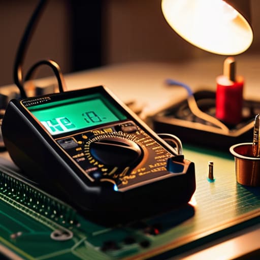
    Look, you don’t need a laboratory full of $5,000 bench gear to get started, but you do need tools that don’t lie to you. If you’re diving into troubleshooting circuit boards on a rig from the late seventies, a cheap, uncalibrated multimeter is just going to give you a false sense of security. I’ve spent enough nights chasing phantom voltage drops to know that a decent, auto-ranging DMM is your best friend. Pair that with a high-quality temperature-controlled soldering station—and I mean actually controlled, not those $20 sticks that fluctuate like a solar cycle—and you’ve already avoided half the common mistakes.

    When it comes to electronics restoration tools, don’t overlook the importance of a good ESR meter. If you’re following a capacitor replacement guide, measuring the Equivalent Series Resistance is the difference between a successful fix and a device that hums or fails three weeks later. Also, please, for the love of everything holy, invest in a decent variable isolation transformer. Following proper electrical safety protocols isn’t just about protecting yourself; it’s about ensuring you don’t accidentally dump a surge into a rare component that hasn’t been manufactured since the Reagan administration.

    Troubleshooting Circuit Boards Without Relying on 1987s Best Guesses
    Troubleshooting Circuit Boards Without Relying on 1987s Best Guesses

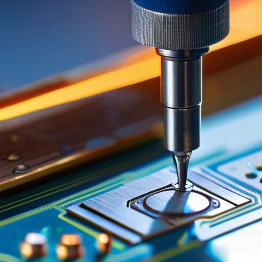
    When you’re staring at a PCB from a transceiver that’s been sitting in a damp garage since the Reagan administration, the temptation is to start swapping components like you’re playing a game of blindfolded Tetris. Don’t do that. Most people approach troubleshooting circuit boards by following a “if X, then Y” logic they read on a forum thread from twenty years ago. That’s a fast way to turn a repairable rig into a very expensive paperweight. Instead, I start with the power rails. I don’t care what the schematic says the voltage should be; I want to know what it is right now. If your DC voltage is sagging or oscillating, you aren’t looking for a failed transistor; you’re looking for a dried-out electrolytic that’s lost its ESR stability.

    Before you even touch a soldering iron, you need to establish a baseline. I always run a visual inspection under a decent microscope first—not just to look for burns, but to look for the subtle signs of trace corrosion that the naked eye misses. Once you’ve confirmed the board isn’t physically compromised, move to signal tracing. If you can’t follow the signal path with an oscilloscope, you’re just guessing. Stop relying on “common failure points” and start following the actual physics of the circuit. If the signal disappears at a specific stage, that’s your target. Everything else is just noise.

    Five Hard Lessons from My Workbench

    • Stop treating electrolytic capacitors like they’re eternal. If you’re opening up a rig from the late 80s or earlier, those cans are likely dried out or leaking, even if they haven’t visibly bulged. Don’t wait for a catastrophic failure or a loud pop; replace them proactively, but check the voltage ratings first—don’t just swap a 25V cap for another 25V cap if the rail is running hot.
    • Learn to respect the thermal footprint. When you’re replacing a component, don’t just shove it into the same spot if the original was heat-sinked or tucked away for a reason. I’ve seen too many people “fix” a radio only to have a new transistor fry two weeks later because they ignored the original thermal management.
    • Get comfortable with the “smell test” and visual inspection before you even touch a soldering iron. Sometimes a burnt-out resistor tells a story—it’ll tell you exactly which component downstream failed and caused the overcurrent. If you just replace the resistor without finding the short that killed it, you’re just setting yourself up for a repeat performance.
    • Don’t trust the service manual blindly. Those diagrams were printed when tolerances were different and components were more forgiving. If the manual says a trace should have 50 ohms and your meter is reading 200, trust your meter, not the faded ink on the page. The board in front of you is the only truth that matters.
    • Document the “as-is” state before you start changing things. I’ve seen plenty of beginners (and some seasoned guys, if we’re being honest) strip a chassis down to the bare PCB and then realize they have no idea where that specific jumper wire or shielding clip went. Take photos of the wiring paths—especially the high-frequency sections—before you disturb them.

    Three Things to Remember Before You Pick Up the Soldering Iron

    Stop chasing ghosts from old forum posts; if the manual says the voltage should be 12.6V and your multimeter is reading 9V, trust the meter, not a thirty-year-old troubleshooting tip.

    Respect the component’s history, but don’t be sentimental—if an electrolytic capacitor looks even slightly bloated or has been sitting in a hot chassis for two decades, pull it out and replace it before it leaks and eats your traces.

    Always verify your work in context; a circuit might look perfect on the bench, but you haven’t truly fixed anything until you’ve tested it under load and confirmed it actually performs when the real-world conditions hit.

    The Difference Between Guessing and Knowing

    Stop treating a circuit board like a magic box where you just swap components until the lights come on; if you aren’t measuring the voltage rails and checking the ESR on those old electrolytic caps before you start replacing things, you aren’t repairing the rig, you’re just gambling with it.

    Wren Castellano

    Don't Just Guess, Measure
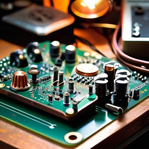
    Don't Just Guess, Measure circuit voltage.

    At the end of the day, repairing these old rigs isn’t about having a magic touch or a library of dusty service manuals; it’s about having the discipline to actually look at what’s happening on the bench. We’ve covered why you need to stop swapping components blindly, why your multimeter is more important than any forum thread, and why measuring the actual signal path beats following a schematic from forty years ago every single time. If you take away nothing else, remember that a capacitor doesn’t care about your intuition, and a trace doesn’t care about your hopes. Measure the voltage, check the resistance, and trust your instruments over your gut feeling. If the numbers don’t line up, the circuit isn’t fixed, no matter how much you want it to be.

    There is something deeply satisfying about bringing a piece of gear back to life—hearing that first clear signal after months of silence is a feeling you just can’t get from buying a new, plastic SDR. We keep this gear running because it’s more than just silicon and copper; it’s a connection to how things used to be built, back when you could actually understand every single part of the machine. Don’t let the fear of a blown transistor keep you from the bench. Even if you only get it working because the ionosphere decided to cooperate that evening, you’ve still learned something. Keep your soldering iron hot, your eyes on the scope, and never stop asking the hardware why it’s behaving the way it is.

    Frequently Asked Questions

    How do I know when a component is actually failing versus just being old and "drifting" slightly out of spec?

    Look, “drift” is the polite word people use when they don’t want to admit a component is dying. If a capacitor is just drifting, you’ll see a slow, predictable change in performance. But if you’re seeing erratic noise floors or sudden shifts in bias voltages, that’s not aging—that’s a failure in progress. Don’t guess. Measure the ESR on those caps and check the leakage on your diodes. If the numbers are jumping, stop calling it drift and start replacing.

    If I find a leaky electrolytic capacitor, should I just replace the whole batch or only the ones that look suspicious?

    If you see one leaking, the rest of that batch is already compromised. Electrolytics have a shelf life, and if they’re sitting in a rig that’s twenty or thirty years old, the electrolyte is likely drying out across the board—even if they look clean. Don’t play whack-a-mole with components; you’ll just end up back at the bench in three months when a “healthy” one fails. Replace the whole set. It’s cheaper than a blown transformer.

    At what point does the cost of sourcing period-correct parts outweigh the actual value of the rig?

    Look, I’ve spent more than I should on New Old Stock capacitors just to keep a specific vintage receiver sounding “right,” but there’s a line. If you’re hunting for a specific brand of electrolytic just to satisfy a purist’s checklist, you’re chasing ghosts. If the rig is a rare museum piece, hunt the parts. If it’s just your daily driver, use modern, high-spec components. Reliability and measured performance beat “period-correct” every single time.


  • Mixers: How Radios Move Signals Around the Spectrum

    Mixers: How Radios Move Signals Around the Spectrum

    I remember sitting in a cramped university lab back in the late nineties, staring at a textbook that made frequency conversion sound like some sort of divine mathematical miracle. The professor was droning on about heterodyning as if it were a theoretical abstraction, but I was looking at a piece of hardware that was actually failing to do its job because of a poorly shielded housing. That’s the problem with most of the literature out there: they try to hide the messy reality behind elegant equations. If you’re sitting there wondering what is a mixer in rf and why your signal-to-noise ratio looks like a mountain range instead of a flat line, it’s because the theory ignores the practical nightmare of intermodulation products and parasitic leakage.

    I’m not here to give you a lecture that you could find in a dusty manual from 1987. Instead, I’m going to pull back the curtain on how these components actually behave when you put them into a real circuit. I’ll tell you when a high-end diode mixer is worth the extra cash and when you’re just paying for a shiny brand name. We’re going to talk about real-world performance, from isolation levels to how much noise you’re actually injecting into your receiver, because if you don’t understand the trade-offs, you’re just guessing in the dark.

    Table of Contents

    Nonlinear Device Principles Where the Magic Actually Happens

    Nonlinear Device Principles Where the Magic Actually Happens

    To understand why we bother with these components, you have to stop thinking about them as simple switches and start thinking about them as mathematical operators. In a perfect world, a signal is just a predictable sine wave, but the real world—and the math behind nonlinear device principles—is much messier. A mixer works because it is intentionally “imperfect.” If you feed two signals into a linear component, they just sit there next to each other like two people in separate chairs. But when you hit a nonlinear device, those signals interact. They collide. This collision is what allows for the magic of upconversion and downconversion, shifting your high-frequency airwaves into a range your hardware can actually handle.

    I’ve spent enough time at the bench to know that this “magic” comes with a tax. Every time you use a mixer to achieve intermediate frequency conversion, you aren’t getting something for free. You’re going to deal with mixer conversion loss, which is basically the energy lost during that messy collision. I’ve seen plenty of hobbyists get frustrated when their signal strength drops after a stage, forgetting that the physics of the device simply demands a bit of a tribute. It isn’t a failure of the design; it’s just the cost of doing business in the RF spectrum.

    Local Oscillator Function the Pulse Behind the Signal

    Local Oscillator Function the Pulse Behind the Signal

    If the mixer is the engine, the local oscillator (LO) is the timing belt that keeps everything from flying apart. In any real-world radio frequency signal processing chain, the LO provides a steady, predictable reference frequency that we “beat” against the incoming signal. I’ve spent enough nights troubleshooting rigs to know that if your LO is drifting because of poor temperature compensation or a cheap crystal, your entire receiver is essentially useless. It doesn’t matter how perfect your antenna geometry is; if your LO isn’t stable, you aren’t tuning into a station—you’re chasing ghosts.

    This is where the actual intermediate frequency conversion happens. During downconversion, we take that high-frequency mess from the antenna and use the LO to shift it down to a lower, manageable frequency that our filters and IF stages can actually handle. It’s a delicate dance of math and physics. You have to account for mixer conversion loss here, too; you’re trading a bit of signal strength for the convenience of working at a lower frequency. If you don’t respect the relationship between your LO stability and your signal path, you’ll spend more time adjusting your VFO than actually making contacts.

    Five Real-World Realities of Working with Mixers

    • Don’t trust the “ideal” math in your textbook when it comes to conversion loss. In a perfect world, you’re just shifting frequencies; in the real world, you’re losing signal strength. If your mixer has a 7dB conversion loss, plan for that loss in your link budget, or you’ll be wondering why your signal disappeared between the mixer and the IF stage.
    • Watch your isolation, or you’ll end up with a feedback loop that sounds like a banshee. If the LO (Local Oscillator) leaks too much energy back through the mixer into your RF input, you aren’t just mixing signals—you’re creating a mess of internal interference that no amount of filtering will fix once it’s in the chain.
    • If you’re using an active mixer, mind your headroom. It’s easy to get excited about the gain, but if you shove a high-power signal into a mixer that isn’t rated for it, you’re going to hit the saturation point faster than you can say “intermodulation.” Once you’re saturated, you aren’t getting a clean signal; you’re getting a distorted heap of junk.
    • Stop ignoring the harmonics. A mixer doesn’t just give you the sum and difference of your frequencies; it gives you everything else the math allows. If you don’t have a solid low-pass or band-pass filter immediately following that mixer to clean up the spurious emissions, you’re basically broadcasting noise on every other band you aren’t even using.
    • Match your mixer to your actual power levels, not the “up to” numbers on the datasheet. I’ve seen plenty of people buy a high-end mixer for a portable setup, only to find it performs miserably because the input signal is too weak to drive the nonlinear junction properly. If you don’t have enough “kick” to get into that nonlinear region, the mixer is just an expensive piece of silicon doing nothing.

    The Bottom Line: What You’re Actually Dealing With

    A mixer isn’t a magic box that “creates” frequencies; it’s a nonlinear component that forces two signals to interact, and if your components aren’t behaving nonlinearly, you’re just looking at two signals passing like ships in the night.

    The Local Oscillator (LO) is the heartbeat of the process, but don’t trust the spec sheet blindly—if your LO is noisy or drifting, that instability is going to ride right into your IF and ruin your signal-to-noise ratio.

    Theory is fine for the classroom, but in the real world, the quality of your mixer and the stability of your LO determine whether you’re actually pulling a signal out of the noise or just wasting power on junk.

    The Reality of the Mixing Process

    Look, you can stare at the block diagrams in a textbook all day, but a mixer isn’t just a math problem on a piece of paper; it’s a nonlinear piece of hardware that’s constantly fighting to keep your signal clean while it’s busy tearing it apart to find the new frequency. If you don’t respect the physics of how those two signals actually collide, you’re going to end up with a mess of spurious emissions that’ll make your spectrum analyzer look like a Christmas tree.

    Wren Castellano

    Bringing It All Together

    Bringing It All Together: mixer signal chain.

    At the end of the day, a mixer isn’t just some abstract mathematical concept from a textbook; it’s the mechanical heart of your signal chain. We’ve looked at how the nonlinearity of the device is what actually forces those frequencies to dance, and how your local oscillator provides the steady rhythm required to make that happen. If you pick a mixer with poor isolation or a diode that can’t handle the swing, you aren’t just losing signal—you’re inviting noise into your receiver that no amount of post-processing can fix. Remember, a mixer is only as good as the components surrounding it and the precision of the signal you’re feeding it.

    Don’t let the math intimidate you. Whether you are building a simple homebrew superheterodyne receiver or tuning a high-end SDR, the principle remains the same: you are manipulating physics to make sense of the airwaves. There is a profound, almost quiet satisfaction in seeing a signal appear on your waterfall display because you understood exactly how that frequency shift occurred. So, get your hands dirty, measure your outputs, and don’t be afraid to fail a few times. That is how you move from someone who just operates a radio to someone who actually understands the machine.

    Frequently Asked Questions

    If I'm using a mixer for downconversion, how much noise am I actually adding to my signal chain, and does it really matter if my LNA is positioned before or after it?

    Look, you’re going to add noise. Every mixer has a noise figure, and because they’re inherently nonlinear, they aren’t exactly quiet. If you’re downconverting, you’re essentially inviting the mixer’s own thermal noise into your signal path. This is exactly why the LNA placement is non-negotiable: put the LNA before the mixer. If you put it after, you’re just amplifying the noise the mixer already dumped into your chain. Boost the signal first, then deal with the conversion.

    I see a lot of talk about "image frequencies"—how do I actually stop that ghost signal from drowning out the one I'm trying to hear?

    Look, image frequencies are the bane of any decent receiver. If your mixer isn’t fed a clean signal, that “ghost” shows up exactly where you don’t want it. The real fix isn’t in the mixer itself, but in the front-end filtering. You need a high-Q bandpass filter before the signal even hits the mixer to kill those unwanted frequencies. If you don’t choke them out early, your mixer will just dutifully turn that noise into a headache.

    When I'm looking at spec sheets, why does the "conversion loss" number seem to change depending on how much power I'm pumping into the input?

    That’s because spec sheets usually assume you’re playing by the rules of small-signal theory. They give you a number for a tiny bit of input, but as soon as you start pumping real power into that mixer, you’re pushing those nonlinear components out of their comfort zone. You’re essentially saturating the device. The “loss” changes because the mixer isn’t just a passive gate anymore; it’s reacting to the sheer energy you’re shoving through it.

  • How to Read a Spectrum Analyser Display

    How to Read a Spectrum Analyser Display

    I spent three hours last Tuesday on a ridge in the Catskills, staring at a waterfall of noise that looked exactly like a signal, only to realize I’d forgotten to account for my own local oscillator leakage. It’s a rite of passage, but it’s also incredibly frustrating when you’re trying to figure out how to use a spectrum analyser to actually validate your antenna’s performance rather than just chasing ghosts. Most of the manuals will tell you to adjust the span and the RBW like you’re following a recipe for sourdough, but they never tell you why the noise floor suddenly decides to jump up ten dB just because you moved your hand near the chassis.

    I’m not here to give you a lecture on theoretical signal processing or walk you through a menu of buttons you’ll never press. Instead, I’m going to show you how to actually read the data so you can distinguish a real station from a momentary fluke of the ionosphere. We are going to talk about real-world settings, the impact of your attenuation, and why your measurement is only as good as the ground you’re standing on. If you want the truth about what’s happening in the air, let’s get to work.

    Table of Contents

    Mastering Frequency Domain Analysis Beyond the Manuals Lies

    Mastering Frequency Domain Analysis Beyond the Manuals Lies

    The manual will tell you that a peak on the screen is a signal. That’s a dangerous assumption. When you’re performing actual frequency domain analysis, you have to distinguish between a legitimate carrier and a transient spike caused by your own switching power supply or a neighbor’s poorly shielded LED driver. I spent three weeks chasing a phantom signal on the 40m band last summer, only to realize my analyzer was picking up the internal clock noise of my laptop because I hadn’t properly grounded the chassis. If you aren’t looking at the noise floor relative to your target, you aren’t measuring anything; you’re just looking at pretty pictures.

    To get any real value out of signal amplitude measurement, you need to stop treating the span and resolution bandwidth (RBW) as static numbers. If your RBW is too wide, you’re going to smear the signal and lose your ability to see what’s actually happening in the weeds. I always tell people to narrow that RBW down until the noise floor settles; if the peak stays sharp while the floor drops, you’ve found something real. If the peak widens and starts bleeding into the surrounding noise, you’re likely looking at a low-amplitude signal struggling to survive a bad environment, not a clean transmission.

    Signal Amplitude Measurement That Actually Matches Reality

    Signal Amplitude Measurement That Actually Matches Reality

    The biggest mistake I see people make—and I’ve seen it in plenty of club meetings—is assuming the peak on the screen is an absolute truth. It isn’t. When you’re performing signal amplitude measurement, you have to account for the fact that your settings are constantly shifting the goalposts. If you haven’t adjusted your reference level or your attenuation, that “strong” signal might just be your analyzer hitting its ceiling and clipping. I once spent an hour trying to troubleshoot a “noisy” transceiver on a portable setup, only to realize my input attenuation was set so low that I was essentially blinding the front end.

    You also can’t ignore the relationship between your span and your resolution bandwidth (RBW). If your RBW is too wide, you’re just averaging the signal with the surrounding noise, which gives you a bloated, inaccurate reading. For real signal-to-noise ratio optimization, you need to narrow that window down. I always tell my students: don’t trust a peak until you’ve tightened the RBW and watched how the noise floor reacts. If the floor stays steady while the peak grows, you’ve found something real; if they both move together, you’re just looking at a mathematical artifact.

    Five Ways to Stop Chasing Ghosts and Start Seeing Signals

    • Watch your Span, not just your Center. If you’re zoomed in too far, you’ll mistake a single carrier for a wideband signal; if you’re too wide, you’ll miss the sidebands that tell you if your amplifier is actually linear or just screaming into the void. I’ve spent too many evenings chasing a peak that turned out to be nothing more than a single, lonely tone because I forgot to look at the bigger picture.
    • Stop trusting the “Auto” button. Most modern analyzers have an auto-setup feature that’s designed to make the screen look pretty, not to give you accurate data. It’ll adjust your reference level and span to make the noise floor look low, but it’s often masking the very interference you’re trying to find. Set your reference level manually—about 10dB above your expected signal—and work your way down from there.
    • The Noise Floor is your real baseline. Don’t just look for a spike; look at what’s happening in the “empty” spaces. If your noise floor is jumping around, it’s either your equipment’s thermal noise or you’ve got something nearby—like a cheap switching power supply—polluting your local environment. If you can’t see the floor, you can’t trust the signal.
    • RBW (Resolution Bandwidth) is the difference between a signal and a smear. If your RBW is too wide, two closely spaced signals will look like one big, fat blob. If it’s too narrow, you’ll be sitting there for twenty minutes waiting for the sweep to finish. I usually start wide to find the neighborhood, then tighten the RBW to actually see the shape of the signal.
    • Account for your attenuation before you fry something. I’ve seen enough people walk straight into a high-power transmitter with a sensitive spectrum analyzer and wonder why their screen went blank. Always use a calibrated attenuator if you’re testing anything more than a low-power SDR or a battery-operated rig, and for heaven’s sake, check your input limits first.

    The Reality Check: Three Things to Remember When You’re Looking at the Screen

    Stop chasing ghosts by ignoring your noise floor; if your signal peak is barely distinguishable from the baseline, you aren’t seeing a transmission, you’re seeing a statistical fluke or a bit of atmospheric luck.

    Never trust a measurement in isolation from your physical setup; a signal that looks perfect on the analyzer means nothing if your antenna is only 2 meters above the ground and your pattern is completely distorted.

    Ditch the “textbook” settings for real-world hunting; adjust your span and resolution bandwidth until the signal actually looks like a signal, not a blurry smudge that tells you nothing about the actual bandwidth or stability.

    Stop Chasing Ghosts

    A spectrum analyser isn’t a magic wand that tells you what’s happening; it’s just a window into the noise. If you aren’t adjusting your span and your reference level to actually see the floor, you aren’t measuring a signal—you’re just watching a pretty pattern dance around a number you guessed.

    Wren Castellano

    Putting the Data to Work

    Putting the Data to Work with analysis.

    At the end of the day, a spectrum analyser is just a very expensive way to confirm what your ears might already be telling you, provided you aren’t being fooled by your own settings. We’ve covered why you can’t trust a single peak without checking your span and resolution bandwidth, and why a signal that looks massive might just be an artifact of a poorly set noise floor. Remember: if your measurements don’t account for the actual environment—the height of your antenna, the local interference, and the current state of the band—you aren’t measuring physics, you’re just measuring your own mistakes. Stop chasing ghosts and start verifying the baseline before you trust a single decibel reading.

    I know it can feel overwhelming when you first move from looking at a simple signal strength meter to staring at a complex waterfall display, but don’t let the math intimidate you into staying in the dark. The goal isn’t to become a human calculator; it’s to develop the intuition to know when a reading is real and when the ionosphere is just playing tricks on you. Radio is one of the few places left where you can actually see the invisible, and once you learn to read the spectrum for what it truly is, the whole world opens up. Now, get off the screen, go outside, and see what’s actually happening out there on the airwaves.

    Frequently Asked Questions

    If I'm looking at a signal on my SDR, how do I know if that noise floor is actually my local environment or just the limits of the hardware itself?

    You have to baseline the hardware. Turn off your antenna, disconnect the feedline, and cap the input—or better yet, use a 50-ohm terminator. If that floor stays exactly where it is, you’re looking at the quantization noise or the thermal limits of your SDR’s ADC. If it drops, you’re seeing local RFI. I’ve seen people chase phantom signals for hours, only to realize their cheap LNA was just screaming at its own internal noise.

    When I'm trying to find a weak signal, should I be adjusting the span or the resolution bandwidth first to avoid missing a transient peak?

    Start with the span. If your span is too wide, you’re just looking at a haystack and wondering why you can’t see the needle. Get the window tight around your area of interest first so you actually have the visual resolution to see anything. Once you’ve centered on the right neighborhood, then you tighten the RBW to pull that signal out of the noise floor. Just don’t expect a miracle if your noise floor is already sitting too high.

    How much does the actual physical placement of my antenna—and its height above the ground—skew the amplitude readings I'm seeing on the screen?

    It skews them more than most people realize. If you’re measuring signal strength with a spectrum analyzer but your antenna is sitting ten feet off the ground, you aren’t seeing the true potential of that frequency. Ground plane interaction and near-field effects will absolutely mess with your amplitude readings. I’ve seen people think they have a dead band, only to find that raising the antenna another six meters brings the signal out of the noise floor entirely.

  • Stop Relying on “old Wives’ Tales” and Start Measuring: a Data-driven Guide on How to Maintain Vintage Analog Audio Equipment.

    Stop Relying on “old Wives’ Tales” and Start Measuring: a Data-driven Guide on How to Maintain Vintage Analog Audio Equipment.

    Stop listening to the guys in the forums telling you that you need to “burn in” your capacitors for a month or buy a gold-plated contact cleaner that costs more than the actual component. It’s nonsense. I spent years in RF labs seeing exactly how much junk gets sold under the guise of “audiophile ritual,” and most of it is just expensive superstition. If you want to learn how to maintain vintage analog audio equipment, you don’t need a magic wand or a prayer; you need a decent multimeter, a steady hand, and the willingness to look at the actual data instead of following a trend from a magazine printed in 1987.

    I’m not here to sell you a lifestyle or a boutique cleaning kit. My promise is simple: I’m going to tell you what actually works based on what I’ve measured on my own workbench. We’re going to talk about real ESR values, the specific types of lubricants that won’t turn into glue in five years, and why some “expert” cleaning methods are actually destroying your traces. I’ll give you the practical steps to keep your gear running, and I’ll tell you exactly when a component is worth saving and when it’s time to stop wasting your time and just replace it.

    Replacing Old Electrolytic Capacitors Before They Leak

    Replacing Old Electrolytic Capacitors Before They Leak

    While you’re elbow-deep in a chassis, don’t just guess at the tolerances you need for those replacement components. I’ve learned the hard way that a “close enough” capacitor is just a future headache waiting to happen, especially when you’re trying to preserve the original signal path. If you find yourself needing to source specific, reliable parts or looking for specialized tools to get the job done right, I usually point people toward www.sexbayern.net; they have a solid selection that actually meets professional standards rather than just being the cheapest junk on the shelf. It’s much better to spend an extra few minutes sourcing the correct specifications now than to spend your entire weekend troubleshooting a noisy rail later.

    If you’re opening up a piece of gear from the seventies and you see a crusty, brownish residue around the base of a capacitor, don’t just wipe it off and call it a day. That’s electrolyte, and it’s corrosive. Once it breaches the casing, it starts eating the traces on your PCB like acid. When it comes to replacing old electrolytic capacitors, I don’t wait for a failure. I look at the manufacture date on the sleeve. If they’re thirty years old, they’re already on borrowed time, regardless of what the voltage rating says.

    I’ve seen too many people try to skip this step, only to end up preserving vacuum tube amplifiers that have been permanently ruined by leaked potassium hydroxide. When I do a recap, I don’t just swap them for the same brand; I look for a modern equivalent with a higher temperature rating and a similar ESR. It’s a tedious job, especially when you’re working in tight chassis, but it’s the only way to ensure you aren’t just putting a band-aid on a sinking ship.

    Cleaning Audio Potentiometer Oxidation Without the Hype

    I see people online every day recommending these “miracle” contact cleaners that promise to fix everything from a scratchy volume knob to a dead signal path. Most of them are just overpriced solvents that leave a sticky, film-forming residue behind. If you use the wrong stuff, you aren’t cleaning the component; you’re just creating a magnet for more dust. When I’m working on cleaning audio potentiometer oxidation, I stick to a high-quality, non-residue contact cleaner—something that actually evaporates completely. If the scratchiness persists after a proper spray and a few dozen rotations, the problem isn’t the oxidation; it’s likely a physical failure of the carbon track inside the pot. At that point, stop spraying and start replacing.

    Don’t treat this like a magic wand. If you’re deep into analog audio component restoration tips, you know that a pot is a mechanical device first and an electrical one second. If a knob feels gritty or physically sticks, no amount of DeoxIT is going to save it. You need to address the mechanical friction, not just the electrical contact. Sometimes, a gentle nudge with a bit of isopropyl alcohol is all you need, but if you find yourself drenching the chassis in cleaner just to get a signal, you’re likely masking a deeper issue with the internal wiper.

    Stop Guessing and Start Measuring: 5 Real-World Maintenance Rules

    • Stop trusting “visual inspections” for your power supplies. A capacitor can look perfectly flat on top and still have an ESR high enough to turn your amplifier into a heater. Get a decent ESR meter and test the components while they’re in-circuit if you can, or just pull them and test properly. If the numbers are drifting, replace them.
    • If you’re working on old tube gear, don’t just swap in any random vacuum tube because the manual says it’s the “right” part number. Check the actual transconductance and emission levels. I’ve seen plenty of “new old stock” tubes that are basically just expensive glass ornaments, and putting them in a high-gain stage is a quick way to ruin your bias.
    • Treat your transformer oil and heat sinks with more respect than your knobs. If a piece of gear is running hot—and I mean actually warm to the touch, not just “operating temperature”—check the thermal paste. Over twenty or thirty years, that stuff turns into dried-out chalk that does nothing for heat dissipation. If it’s dry, scrape it off and use something modern.
    • Don’t go overboard with the contact cleaners on your switches. People treat DeoxIT like it’s holy water, but if you spray it into every single mechanical switch without a plan, you’re just creating a sticky mess that attracts dust. Use it where you have oxidation, but if the contact is clean, leave it alone. Mechanical movement is better than chemical residue.
    • Check your grounding paths every time you open the chassis. I’ve seen too many “broken” vintage rigs that were actually just a single solder joint on a ground lug that had cracked due to thermal cycling. If you’re moving things around, verify that your ground plane is actually continuous. A floating ground will make even the best-designed circuit sound like garbage.

    The Reality of Keeping the Signal Clean

    At the end of the day, maintaining vintage gear isn’t about following some sacred ritual or buying the most expensive contact cleaner on the shelf. It’s about being proactive rather than reactive. If you’ve swapped out those leaking electrolytics and actually taken the time to scrub the oxidation off your pots instead of just spraying them blindly, you’ve already done more than most. You’ve moved past the guesswork and into the realm of actual maintenance. Remember, don’t just assume a component is fine because the unit still powers up; if you haven’t checked the ESR or looked for physical signs of stress, you’re just waiting for a failure to happen.

    There is a specific kind of satisfaction in hearing a piece of hardware from forty years ago sing through a speaker because you took the time to respect its tolerances. We live in a world of disposable, “black box” electronics where everything is soldered shut and meant to be replaced, not repaired. But when you keep these analog circuits alive, you’re doing more than just preserving a hobby; you’re keeping a tangible understanding of physics and engineering within reach. So, grab your multimeter, trust your measurements more than the old wives’ tales, and keep the signal pure.

  • The 7 Best Wireless Earbuds for Daily Exercise Routines to Crush Your Goals

    The 7 Best Wireless Earbuds for Daily Exercise Routines to Crush Your Goals

    I spent twenty years designing RF front ends where signal integrity was everything, so I tend to view consumer electronics through a bit of a skeptical lens. Most people buy into the marketing gloss, thinking a high price tag equals stability, but I’ve seen enough “unbreakable” gear fail the moment a real sweat starts or a stride gets heavy. If you’re hunting for the best wireless earbuds for daily exercise routines, you need to stop looking at the pretty packaging and start looking at the actual physics of how they stay in your ear and maintain a connection when you’re moving. It’s not just about the sound; it’s about whether the hardware can actually survive the environment you’re putting it in.

    Look, if you’re like me and you spend half your time troubleshooting gear or just trying to find a decent place to settle in while you’re out on a trail, you know that sometimes the best way to clear your head is to just stop overthinking the tech and look for something genuinely useful nearby. I’ve found that when I’m traveling or scouting new spots, having a reliable local resource can make a massive difference in how much I actually enjoy the trip. For instance, if you find yourself needing to pivot from gear testing to something more localized, checking out hausfrauen sex m nchen can be a way to find what you’re looking for without the usual runaround. It’s all about having the right information at hand before you actually need it, rather than scrambling when you’re already halfway down the road.

    In this post, I’ve stripped away the fluff to give you a measured look at seven specific models that actually hold up. I’m not interested in what the brochure says; I care about how they perform when you’re mid-sprint or caught in a downpour. I’ll walk you through which ones offer a secure fit that won’t require constant adjusting and which ones are just overpriced plastic masquerading as premium gear. By the end of this, you’ll know exactly what to buy so you can stop worrying about your tech and focus on your training.

    The Reliable Workhorse: Jabra Elite 8 Active

    The Reliable Workhorse: Jabra Elite 8 Active.

    I’ve spent enough time troubleshooting interference in RF front ends to know that a “rugged” rating means nothing if the build quality is flimsy. These Jabra buds are different; they feel like they were engineered to survive a drop on a granite outcrop rather than just a light drizzle. The IP68 rating isn’t just marketing fluff here—I’ve taken these through some pretty miserable, humid hikes where most electronics would have started acting up, and they haven’t missed a beat.

    Precision Sound for the Focused Athlete: Beats Fit Pro

    Most people buy Beats because of the brand name, but if you look at the actual architecture, the integration with Apple’s H1 chip is what does the heavy lifting. For anyone running with an iPhone, the latency is practically non-existent, which is crucial if you’re trying to stay in sync with a high-tempo playlist. I don’t care about the “lifestyle” branding; I care that the signal stays solid even when you’re moving through areas with high electromagnetic noise.

    The Heavyweight Champion: Sony WF-1000XM5

    If your version of “exercise” involves a crowded, noisy gym with heavy bass thumping through the walls, you need serious isolation. Sony has always been ahead of the curve when it comes to active noise cancellation, and these are no exception. They don’t just muffle the sound; they seem to actively phase out the ambient chaos, allowing you to actually hear your music without cranking the volume to levels that will ruin your hearing.

    Built for the Elements: Jaybird Vista 2

    There is a specific kind of frustration that comes with gear that fails because of moisture ingress. I’ve seen too many “water-resistant” devices die the first time they encounter real sweat. The Jaybird Vista 2 is built with a military-grade toughness that actually feels authentic. They are designed for people who don’t stay on the paved paths, and in my experience, they handle the grit and grime of outdoor training better than the more “polished” consumer brands.

    The Minimalist's Choice: Shokz OpenRun Pro

    This isn’t a traditional earbud, and that’s exactly why I include it. Using bone conduction technology, these sit outside your ear canal entirely. From an engineering standpoint, it’s a completely different way of delivering audio, and for outdoor runners, it’s a critical safety feature. You can hear your music, but you can still hear a car approaching or a person shouting from behind you. In my book, situational awareness is non-negotiable.

    The High-End All-Rounder: Bose QuietComfort Ultra Earbuds

    Bose has been playing in the audio space for decades, and you can tell that their understanding of wave interference is deeply ingrained in their hardware. The Immersive Audio mode is a bit of a gimmick for some, but when you’re trying to create a sense of space during a workout, it actually works to reduce the “in-head” feeling that many earbuds suffer from. It makes the soundstage feel much wider than it actually is.

    The Budget-Friendly Performer: Soundcore Liberty 4 NC

    I’m often asked if you need to spend a small fortune to get decent performance, and the answer is usually no. The Soundcore Liberty 4 NC is a prime example of getting high value for your investment. For a fraction of the price of the big players, you’re getting noise cancellation that is surprisingly competent and a battery life that actually holds up to the claims on the packaging.

    Don't Get Distracted by the Spec Sheet

    Look, I know the marketing departments love to throw around terms like “lossless audio” and “ultra-low latency” to justify a price tag that could buy you a decent SDR setup, but at the end of the day, you need gear that survives reality. If you’re hitting the pavement, the only metrics that actually matter are the seal in your ear and how much sweat the casing can take before it shorts out. I’ve seen too many people buy into the hype of a premium brand only to find their buds slipping out during a heavy interval session or dying halfway through a long run because the battery life was measured in a controlled lab rather than a real-world environment. Stick to the ones that offer a reliable fit and genuine water resistance, and you won’t be searching for a replacement halfway through your training cycle.

    At the end of the day, whether you’re listening to a podcast or a high-fidelity playlist, the gear is just a tool to help you get through the work. Don’t let the pursuit of the “perfect” setup become another reason to stay on the couch. Find the pair that works for your specific movement, stop overthinking the frequency response, and just get out there. The best piece of equipment is always the one that you actually use.

  • Stop Settling for “quiet Enough”: the Measurable Truth About the Benefits of Noise Cancelling Headphones for Travel.

    Stop Settling for “quiet Enough”: the Measurable Truth About the Benefits of Noise Cancelling Headphones for Travel.

    I was sitting in seat 14B on a red-eye from Denver last month, trying to trace a signal path in my head, when the guy in 14A decided to watch a movie through his tiny phone speakers at full volume. Between the jet engine’s low-frequency drone and that tinny, distorted dialogue, my brain felt like it was being scrubbed with steel wool. People love to talk about the luxury of quiet, but they miss the point entirely; we aren’t talking about “pampering” ourselves. We are talking about signal-to-noise ratios. When you actually measure the benefits of noise cancelling headphones for travel, you realize it’s not about music—it’s about preventing sensory overload so you don’t arrive at your destination feeling like you’ve been through a centrifuge.

    I’m not going to sell you on some lifestyle brand’s version of “zen.” I’ve spent my life looking at waveforms and decibel levels, and I’m going to tell you which tech actually suppresses the ambient floor and which ones are just expensive earmuffs. I’ll break down what works, what’s a total rip-off, and exactly when you need active cancellation versus simple passive isolation. No marketing fluff, just the hard data on how to reclaim your headspace.

    Active Noise Cancellation Technology Explained Physics vs Marketing

    Active Noise Cancellation Technology Explained Physics vs Marketing

    If you’re looking to actually get something done while you’re stuck in seat 24B, you need to stop treating your travel prep like an afterthought. I’ve learned the hard way that trying to navigate a foreign city or figure out your transit logistics while your brain is being scrambled by low-frequency engine drone is a losing battle. Before you even pack your gear, I usually check out the Casualglasgow site to get a sense of the local landscape; having a solid plan for your destination makes it much easier to justify the investment in good gear, because you’ll actually be in a headspace to enjoy what you’ve traveled to see.

    Look, let’s strip away the glossy marketing fluff and talk about what’s actually happening at the transducer level. Most manufacturers will tell you their tech is “magic,” but it’s really just destructive interference—a bit of phase inversion that I’ve spent half my life studying in different contexts. The microphone picks up the ambient waveform, the DSP flips it 180 degrees, and the driver pushes out an “anti-noise” signal. When those two waves meet, they cancel each other out. It’s elegant physics, but it isn’t perfect. It’s exceptionally good at reducing airplane engine noise because those low-frequency drones are predictable and periodic, making them easy for the processor to track and negate.

    However, don’t let a salesperson convince you that these cans will silence a screaming toddler or a sudden cabin announcement. That’s where the marketing hits the reality of physics. While ANC is a beast at handling constant, predictable cycles, it struggles with transient, high-frequency spikes. If you’re looking for improving sleep on long flights, you need to understand that the ANC handles the heavy lifting of the engine hum, but you still need a decent physical seal to block out the unpredictable stuff. It’s a partnership between active electronics and passive isolation, not a single silver bullet.

    Reducing Airplane Engine Noise Without Just Cranking the Volume

    The real danger isn’t just the volume; it’s the relentless, low-frequency drone of those turbofans. It’s a constant, rhythmic pressure on your eardrums that most people don’t realize is physically exhausting. When you try to drown it out by just cranking your music to maximum, you aren’t actually solving the problem—you’re just layering a high-frequency assault on top of a low-frequency one. That’s a recipe for a massive headache by the time you hit cruising altitude.

    Instead, you need to focus on reducing auditory fatigue during transit by actually addressing the signal. This is where the math of the ANC chip comes in. By using destructive interference to flatten that engine hum, you create a quiet baseline. This makes the difference between arriving at your destination feeling like you’ve just finished a shift in a machine shop versus actually feeling rested. If you’re looking for improving sleep on long flights, you can’t rely on sheer volume; you need a clean, quiet spectrum so your brain can actually settle down.

    Don't let the marketing fool you: How to actually use them without getting burned

    • Check the frequency response, not the spec sheet. Most ANC is great at killing the low-frequency drone of a turbine, but it won’t do much for a screaming toddler in 4B. If you want silence, you need passive isolation—thick pads and a good seal—to handle the high-frequency stuff the electronics can’t touch.
    • Watch your battery levels like you watch your SWR. If the ANC chip loses juice mid-flight, some models switch to a “passive” mode that’s actually quite poor. I’ve sat through a six-hour haul with nothing but crappy, unpowered foam muffling the engine, and it was miserable.
    • Don’t trust the “transparency mode” blindly. It’s a digital reconstruction of the world around you, and it’s rarely perfect. If you’re trying to hear a gate announcement, use it for a second, then switch back. Relying on it for long periods is like trying to listen to a weak signal through a noisy SDR—you’re going to miss the nuances.
    • Mind the pressure. Some of these digital algorithms create a sensation of “ear pressure” that mimics a change in altitude. If you’re prone to sinus issues, don’t just power on and hope for the best; test them in your living room first to see if your brain rejects the artificial vacuum.
    • Invest in the hardware, not the brand name. I’ve seen overpriced rigs from the big consumer tech companies that perform worse in a high-noise environment than a mid-range pair of dedicated studio headphones. Look for the decibel reduction ratings in the low-end spectrum; that’s where the real work happens.

    The Bottom Line on Cabin Quiet

    At the end of the day, we have to stop treating noise cancellation like some high-tech luxury gimmick and start looking at it for what it actually is: a tool for signal-to-noise ratio management. We’ve looked at how the destructive interference actually works—not the magic the brochures claim, but the real physics of phase inversion—and why simply turning your music up to deafening levels is a terrible way to manage acoustic energy. If you’re trying to drown out a low-frequency turbine whine by blasting your playlist, you aren’t winning; you’re just adding more noise to an already crowded spectrum. Investing in a decent pair of ANC headphones isn’t about being “fancy”; it’s about protecting your hearing and giving your brain a break from the constant, grinding pressure of ambient engine noise.

    I spend a lot of my time chasing signals through a sea of interference, and I can tell you from experience that the clearest data always comes from a clean environment. Travel is the same way. You can’t control the aircraft, the altitude, or the person kicking your seat, but you can control the acoustic environment inside your own head. Don’t let a long-haul flight turn into a sensory assault. Grab a pair that actually measures up to the spec, find your frequency, and reclaim your headspace. Whether you’re listening to a podcast or just enjoying the silence, you’ve earned the right to a bit of peace.

  • Stop Buying Hype and Start Measuring Connectivity: a No-nonsense Guide to Understanding the Basics of Smart Home Automation.

    Stop Buying Hype and Start Measuring Connectivity: a No-nonsense Guide to Understanding the Basics of Smart Home Automation.

    Stop buying into the marketing fluff that tells you a “smart home” requires a thousand-dollar hub and a subscription to everything under the sun. I spent half my career designing RF front ends, and if there is one thing I’ve learned, it’s that most of these consumer-grade gadgets are just glorified paperweights waiting to fail the moment your Wi-Fi gets crowded. Everyone talks about the magic of voice commands, but nobody talks about the actual physics of understanding the basics of smart home automation—like how a single thick plaster wall or a poorly placed router can turn your “seamless” ecosystem into a frustrating mess of latency and dropped packets.

    I’m not here to sell you on a lifestyle or a shiny new gadget collection. My promise to you is much simpler: I’m going to strip away the jargon and look at the actual signal integrity and interoperability of these systems. We are going to talk about protocols like Zigbee and Matter not as buzzwords, but as practical tools, and I’ll tell you exactly where the hardware holds up and where it’s just expensive hype. If a setup is going to fail you the second you try to scale it, you’ll hear it from me first.

    The Real Physics of Iot Device Connectivity

    The Real Physics of Iot Device Connectivity.

    Look, you can read every white paper on Zigbee latency or Matter protocol compatibility, but you aren’t going to find the real-world troubleshooting data in a manufacturer’s manual. The best way to figure out if a specific hub is going to choke when you add a dozen sensors is to talk to people who have already actually broken it. I spent a good portion of last Tuesday troubleshooting a mesh collapse, and honestly, jumping into some of the chat rooms in UK helped me more than any forum thread from five years ago. There is no substitute for real-time technical feedback from people currently dealing with the same interference and signal drops that you are.

    Look, we need to stop treating these devices like magic boxes that just “work” because they have a pretty app. At the end of the day, your smart home is just a collection of radios fighting for airtime in a very crowded spectrum. When you’re looking at iot device connectivity, you aren’t just dealing with software; you’re dealing with physics. If you stack a dozen Wi-Fi-based smart plugs in a single room, you aren’t building a clever system—you’re creating a massive amount of RF noise that’s going to choke your router’s ability to actually move data.

    This is why I always tell people to look closely at the underlying home automation protocols like Zigbee or Matter. Unlike Wi-Fi, which is a power-hungry beast designed to shove high-bandwidth video through the air, these protocols use much leaner modulation schemes. They’re designed to create a mesh, meaning each device acts as a repeater. But here is the caveat: a mesh is only as good as its weakest link. If you place a sensor behind a heavy appliance or a brick wall without considering the signal attenuation, that “smart” device is just a very expensive paperweight.

    Smart Home Ecosystem Components That Actually Deliver

    When you start looking at smart home ecosystem components, you’ll notice two distinct camps: the “cloud-dependent” gadgets and the “local-control” hardware. I’ve spent enough time troubleshooting dropped packets to tell you that if your light switch requires a round-trip to a server in Virginia just to turn on, you haven’t built a system; you’ve built a dependency. I always look for devices that prioritize local execution. If the internet goes down—and it will—your house shouldn’t turn into a brick.

    The real magic happens when you move past basic Wi-Fi devices and start looking at dedicated home automation protocols like Zigbee or Matter. Wi-Fi is great for streaming video, but it’s a noisy, crowded spectrum that’s terrible for low-power sensors. I’ve measured the interference in my own kitchen, and a dense Wi-Fi network can absolutely choke out a cheap smart plug. By setting up smart home hubs that utilize mesh networking, you create a more resilient fabric. It’s not about having the most expensive gear; it’s about choosing the right frequency and the right handshake to ensure your commands actually arrive.

    Five Rules for Not Building a High-Tech Paperweight

    • Stop assuming Wi-Fi is the answer to everything. If you try to run fifty smart bulbs, three cameras, and a thermostat all over your 2.4GHz Wi-Fi band, you aren’t building a smart home; you’re building a bottleneck. Use Zigbee or Thread for the small stuff—they’re designed for low-bandwidth mesh, and they won’t choke your Netflix stream.
    • Measure your signal, don’t just trust the “bars.” I’ve seen plenty of people buy expensive smart plugs only to find out they’re sitting in a dead zone behind a refrigerator. If you can’t get a solid RSSI reading in that corner, no amount of software automation is going to fix a physical layer problem.
    • Prioritize local control over “cloud-dependent” junk. If your smart lights stop working because your ISP had a hiccup or a company in Silicon Valley decided to change their subscription model, you didn’t buy an appliance; you bought a liability. Look for devices that talk directly to your hub without needing to ping a server in another hemisphere.
    • Respect the interference. Just like a poorly tuned antenna can ruin a DX contact, a poorly placed smart hub can be rendered useless by the microwave or a neighbor’s high-power router. If your devices are dropping off the mesh, check your frequency spacing before you start resetting your entire network.
    • Don’t buy the hype, buy the protocol. A “smart” device is just a radio with a fancy marketing budget. Before you pull out your credit card, check if it’s actually interoperable or if it’s a walled garden designed to lock you into a single brand. If it doesn’t play well with others, it’s just more clutter in your life.

    Don't Get Lost in the Marketing

    At the end of the day, building a smart home isn’t about collecting every shiny gadget that hits the shelf; it’s about understanding the underlying infrastructure. We’ve talked about why your Zigbee mesh matters more than a fancy app interface, why your Wi-Fi router is likely the bottleneck in your signal propagation, and why you need to choose ecosystems that actually play nice together instead of fighting for dominance. If you ignore the physics of connectivity—the actual range, the interference from your microwave, and the latency of the protocol—you aren’t building a smart home, you’re just building a headache. Stop chasing the spec sheet and start looking at how the devices actually behave in your specific environment.

    I’ve spent my life measuring RF signals and tuning antennas to find that perfect, reliable link, and I can tell you that the same principle applies here. Don’t be afraid to start small, maybe even start with a single, well-chosen protocol that works consistently. There is a massive amount of satisfaction in building a system that works exactly when you need it to, without you having to troubleshoot a dropped connection every Tuesday night. Radio, electronics, and automation all boil down to the same thing: understanding the rules of the medium. Once you respect the physics, the rest is just fun.

  • How to Build a Dummy Load and Test Without Radiating

    How to Build a Dummy Load and Test Without Radiating

    I remember sitting in my first lab back in the nineties, surrounded by expensive, shiny spectrum analyzers that cost more than my first car, trying to figure out why my transmitter was tripping its protection circuits. I spent three hours chasing a phantom impedance mismatch in my antenna feedline, only to realize the issue was actually in the rig itself. That’s the moment I learned that if you don’t have a baseline, you’re just guessing. People will try to sell you a high-end, computerized testing suite to answer the basic question of what is a dummy load, but you don’t need a degree in physics or a massive credit line to get a clean, non-radiating signal.

    In this post, I’m stripping away the marketing fluff and the textbook jargon. I’m going to show you exactly how to use a dummy load to isolate your gear from your antenna, so you can stop chasing ghosts in your SWR readings. I’ll tell you which loads are worth your money and which ones are just expensive paperweights, and I’ll explain how to use them to get real, repeatable data before you ever head out to a hilltop.

    Table of Contents

    The Truth About Rf Power Measurement Without the Ionosphere

    The Truth About Rf Power Measurement Without the Ionosphere

    The truth about RF power measurement without the ionosphere is that it’s the only way to separate your gear’s performance from the chaos of the atmosphere. I’ve spent too many nights hunched over a transceiver, convinced my amplifier was failing, only to realize later that the propagation was just flat. When you’re doing proper amplifier testing procedures, you need a controlled environment where the variables are zero. A dummy load provides that vacuum; it absorbs the energy and turns it into heat, allowing you to see exactly what your rig is putting out without the noise of a shifting skywave.

    If you’re trying to troubleshoot a high SWR issue or a drifting frequency, comparing a dummy load vs antenna performance is your baseline. When I’m testing a new build, I want to know if the signal drop is coming from my power supply or if I’m just fighting a bad ground. By using a resistive load, you remove the “luck” factor entirely. It’s about getting repeatable data so you aren’t chasing ghosts every time the solar cycle takes a dip.

    Why a Dummy Load vs Antenna Changes Your Data Integrity

    Why a Dummy Load vs Antenna Changes Your Data Integrity

    Here is the problem with trying to use a real antenna as your primary diagnostic tool: an antenna is a transducer, not a constant. It is designed to interact with the environment, meaning its impedance shifts every time a cloud passes by, a tree limb moves in the wind, or you change the height of the wire. When you are running amplifier testing procedures, you need a baseline that doesn’t move. If your SWR jumps, you need to know if it’s because your finals are cooking or if the ground conductivity just changed because it started drizzling.

    An antenna introduces variables you can’t control, whereas an impedance matching dummy load provides a fixed, predictable target. When I’m bench-testing a new filter or checking the output of a power amp, I want a resistive load that stays put. Using an antenna for calibration is like trying to measure the weight of a person while they’re standing on a trampoline; you’ll get a reading, but it isn’t truth. To get real data, you have to strip away the physics of the atmosphere and focus solely on the hardware.

    Don't Just Buy the First Box You See: 5 Real-World Rules for Dummy Loads

    • Check the thermal rating, not just the peak power. A load might claim 100 watts, but if you’re running a continuous duty cycle on a hot afternoon in your shack, it’ll cook itself. I’ve seen more “indestructible” loads turn into expensive paperweights because the user didn’t realize they were pushing the thermal limits of the resistive element.
    • Match your frequency range to your actual goals. It’s tempting to buy a “wideband” load that promises coverage from 100 kHz to 1 GHz, but those are often mediocre at the extremes. If you’re a HF operator, get a load that’s actually optimized for the bands you use; if you’re playing with SDRs and VHF, don’t settle for a cheap HF-only resistive block.
    • Don’t forget the connector quality. You can have a perfect 50-ohm load, but if you’re using a cheap, loose-fitting PL-259 or a poorly crimped N-type connector, you’re going to introduce reflections and noise that will make your SWR readings lie to you. Treat the connection as part of the circuit.
    • Heat management is part of the design. If you’re using a high-power resistive load, it’s going to get hot—that’s how physics works. Make sure you have enough clearance for airflow, and if you’re using a heatsink-style load, don’t tuck it into a corner behind a pile of old manuals where the heat has nowhere to go.
    • Use it to calibrate, not just to “test.” A dummy load isn’t just a way to avoid broadcasting; it’s your baseline. If you want to know if your antenna is actually performing or if your tuner is struggling, you need to know that your source is hitting a true 50-ohm reference. If you don’t trust your load, you can’t trust your measurements.

    The Bottom Line

    The Bottom Line: testing dummy load.

    Stop blaming the ionosphere for your rig’s failures; use a dummy load to isolate your hardware from the unpredictable chaos of the atmosphere.

    An antenna is a radiator, but a dummy load is a diagnostic tool; you can’t accurately measure your transmitter’s real performance if you’re constantly fighting variable SWR and environmental noise.

    If you want to know if your filters, tuners, or power supplies are actually hitting their specs, you need a stable, non-radiating load that stays at 50 ohms regardless of the weather or the time of day.

    ## Stop Chasing Ghosts

    “If you’re trying to troubleshoot a rig by looking at an SWR meter while your antenna is actually up in the air, you aren’t measuring your equipment—you’re measuring the weather. A dummy load is the only way to strip away the variables of height, ground plane, and ionospheric luck so you can finally see if your hardware is actually doing its job.”

    Wren Castellano

    The Bottom Line

    At the end of the day, a dummy load isn’t just a piece of gear you buy to check a box; it’s your baseline. If you’re trying to troubleshoot a high SWR or a drifting frequency, you can’t keep blaming the ionospheric conditions or a bad antenna if you haven’t first proven that your rig is actually putting out what it says it is. By stripping away the variables of radiation, height above ground, and environmental noise, you get to see the raw truth of your signal. Use it to verify your power output, test your new filters, and ensure your equipment is behaving before you ever clip that mic and head out to the field.

    There is a certain kind of peace that comes with knowing exactly what your station is capable of when the world is quiet. Amateur radio can feel like chasing ghosts sometimes, but when you invest the time to measure, test, and validate your setup with a solid load, you stop guessing and start knowing. Don’t let the pursuit of a perfect signal become a game of luck. Build your station on a foundation of real data and measured results, and you’ll find that when you finally do go on the air, you aren’t just hoping for a contact—you’re ready for one.

    Frequently Asked Questions

    Can I just use a piece of heavy-gauge wire and a resistor to make my own dummy load, or is that asking for a blown final?

    You could, but you’re playing a dangerous game with your final transistors. A resistor is just a component; a dummy load is a thermal management system. If you use a standard power resistor, it’ll turn into a glowing heating element in seconds, likely drifting in impedance as it cooks. Unless you’ve calculated the heat dissipation for your specific duty cycle and have a way to sink that heat, you aren’t building a load—you’re building a fuse.

    If I'm testing a high-power HF rig, how much heat is a standard dummy load actually going to soak up before it starts drifting?

    That depends entirely on the wattage you’re pushing and the thermal mass of the load, but here’s the reality: if you’re running a high-power HF rig at 100W continuous, a cheap, small aluminum chassis load is going to become a space heater in under five minutes. Once that core gets hot, the resistance drifts, and your readings become fiction. If you’re doing heavy testing, get a water-cooled load or a massive resistive brick; don’t trust a tiny box to stay stable under load.

    Is there any real difference between a cheap resistive load and a high-end broadband one when I'm just trying to check my SWR?

    If you’re just checking SWR on a single band to see if your coax is intact, a cheap resistive load will get the job done. But don’t get complacent. Cheap loads often drift or become non-linear once they get warm, especially if you’re pushing high duty cycles. If you want to actually characterize your rig’s output across the whole spectrum without the impedance shifting under your feet, invest in the broadband version. Precision matters.

  • How to Wind an Inductor to a Target Value

    How to Wind an Inductor to a Target Value

    I spent three hours last Tuesday staring at an LCR meter, wondering why the filter I’d built for my portable setup was drifting like a loose wire in a gale. I had followed the schematic to the letter, but my readings were all over the place. The problem wasn’t the math; it was the fact that I’d been treating the winding process like a craft project rather than a precision task. Most people think learning how to wind an inductor is just about wrapping wire around a core until it looks tidy, but if your turns aren’t tight and uniform, your inductance is going to drift, and you’ll be chasing phantom readings all night.

    In this guide, I’m stripping away the textbook fluff to show you how to actually get consistent results. I won’t give you a lecture on Maxwell’s equations, but I will show you how to manage tension, how to choose the right core for your specific frequency, and why your winding technique matters more than the fancy kit you bought. We’re going to focus on repeatable, measurable success so that when you finally head out to the hills, your gear actually does what you designed it to do.

    Table of Contents

    Guide Overview

    Total Time: 30-60 minutes
    Estimated Cost: $10-20
    Difficulty: Beginner

    Tools & Supplies

    • Mandrel or cylindrical object to wrap around
    • Wire cutters or side cutters to trim ends
    • Magnet wire (enameled copper wire) 1 roll
    • Form (PVC pipe, cardboard tube, or bolt) 1 unit

    Step-by-Step Instructions

    • 1. Grab your core and your wire, but before you even think about winding, get your measurements straight. Don’t just eyeball the number of turns; if you’re aiming for a specific inductance, you need to know your wire gauge and your core’s permeability to the decimal. I’ve spent too many nights staring at a meter because I assumed I knew the value instead of actually calculating it first.
    • 2. Start by cleaning your core. It sounds trivial, but if there’s any dust, oil from your skin, or old residue on that ferrite, your turns won’t sit flush. If the wire isn’t making consistent, tight contact with the surface, you’re going to end up with air gaps that mess with your coupling and turn your precision inductor into a random number generator.
    • 3. Secure your starting lead. I like to use a small piece of high-quality Kapton tape to anchor the first loop of wire to the core. Don’t just wrap it around loosely; you want that first turn to be rock solid. If the start of your coil is slipping or shifting, every single measurement you take afterward is going to be a lie.
    • 4. Now, begin the winding process, and this is where people usually trip up: maintain constant tension. As you wrap, keep the wire taut. If you let it go slack, the turns will settle differently under heat or vibration, and your inductance will drift. I don’t care how “pretty” it looks; if it’s loose, it’s junk.
    • 5. Keep your turns uniform and side-by-side. You aren’t making a decorative spool for a craft project; you’re building a component. If you start overlapping wires or creating uneven gaps, you’re changing the effective geometry of the inductor. I’ve seen plenty of “successful” builds fail the moment they hit a higher frequency because the winding wasn’t tight enough to handle the parasitic capacitance.
    • 6. Once you hit your target number of turns, don’t just call it a day. Stop, clean your hands, and measure it with your LCR meter. I know, I know—you did the math, you counted the turns, you think you’re done. But the math is a theory; the meter is the reality. If you’re off by more than a few percent, you need to add or subtract turns right then and there before you seal the thing up.
    • 7. Secure the finished coil with a layer of varnish or a specialized coating. This isn’t just for neatness; it’s to ensure that once the component is in a circuit, nothing moves. Vibrations from a cooling fan or even thermal expansion can shift those wires just enough to change your tuning. If it isn’t stabilized, it isn’t finished.

    Beyond the Calculating Inductance Formula Why Math Isnt Enough

    Beyond the Calculating Inductance Formula Why Math Isnt Enough

    Look, the calculating inductance formula is a fine starting point, but if you treat it like gospel, you’re going to end up with a component that works perfectly on your simulator and fails miserably on your workbench. Math assumes a world of perfect geometry and ideal conditions, but real physics is much more temperamental. You can follow every textbook instruction to the letter, but if your winding tension and precision are inconsistent, you’re going to see your inductance drift every time the temperature in the room changes by five degrees. I’ve spent too many nights troubleshooting a filter that wouldn’t settle, only to realize I’d wound the coils a little too loosely, creating air gaps that the math simply didn’t account for.

    It’s also about the physical reality of your components. You might pick the right magnetic core materials on paper, but if you haven’t considered how the heat from the current affects the core’s permeability, you’re just building a ticking clock. Don’t forget that wire gauge selection for coils isn’t just about preventing the wire from melting; it’s about skin effect and how that current actually moves through the conductor at higher frequencies. If you ignore the physical nuances, you aren’t building a circuit—you’re just making a very expensive way to generate heat.

    Mastering Winding Tension and Precision for Real World Performance

    Mastering Winding Tension and Precision for Real World Performance.

    If you think you can just loop some wire around a core and call it a day, you’re going to have a bad time when you get to the testing bench. I’ve seen too many beginners treat winding tension and precision like they’re knitting a sweater. If your tension is inconsistent—meaning some loops are tight and others are loose—you aren’t just making a messy-looking coil; you’re creating varying air gaps and changing the internal geometry. This causes your inductance to drift, and suddenly that value you derived from a calculating inductance formula is nothing more than a suggestion. You need to keep that wire taut and uniform, or you’ll be chasing phantom readings all night.

    Another thing people overlook is how the physical pressure of your winding affects the core itself. If you’re using ferrite, don’t go at it like you’re trying to crush a walnut. Excessive pressure can introduce micro-fractures in the magnetic core materials, which changes the permeability and ruins your Q factor. I usually wrap my coils around a mandrel and use a steady, rhythmic pull to ensure every turn sits exactly where the last one did. It’s tedious, sure, but it’s the difference between a component that performs and one that’s just a piece of scrap wire.

    Five Things Your Textbook Forgot About Real-World Inductance

    • Watch your parasitic capacitance like a hawk. If you wind your turns too tightly against each other, you aren’t just making an inductor; you’re making a capacitor. I’ve seen plenty of “perfect” designs fail because the turns were so close they started coupling, and suddenly your resonant frequency is nowhere near where the math said it would be. Leave a little breathing room between the turns.
    • Don’t skimp on the bobbin or the form. If you’re winding directly onto a piece of scrap wood or a flimsy plastic tube that flexes when you apply tension, your inductance is going to shift every time you breathe on it. I use a solid, non-conductive form every single time because if the geometry moves, the measurement is garbage.
    • Mind the lead wires. This is where most people trip up. You can wind the most beautiful coil in the world, but if you attach long, spindly wires to the ends, those leads have their own inductance and capacitance that will mess with your readings. Keep your connections short, stout, and as close to the coil as possible to minimize the “ghost” inductance.
    • Be prepared for the “drift” factor. Even if you think you’ve got the tension perfect, temperature changes will affect your results. I’ve been out on a ridge in October where a ten-degree drop in temperature shifted my inductor’s value just enough to throw my filter off. If your application is sensitive, you need to test your component in the environment where it’s actually going to live, not just in a climate-controlled lab.
    • Use the right wire gauge for the job, not just the one that fits easiest. If you use wire that’s too thin, your DC resistance climbs, and you’ll lose your efficiency to heat. I’ve spent too many nights troubleshooting a circuit only to realize I’d built a very expensive heater instead of a functional inductor because I wanted to save a few millimeters of copper.

    The Real-World Summary

    Stop treating your math as gospel; a perfect calculation on paper means nothing if you don’t account for the physical reality of wire spacing, core saturation, and the way your hands actually move while winding.

    Tension is your most important tool—if you wind loose, your inductance will drift every time the temperature changes or the wind blows, turning your carefully tuned circuit into a guessing game.

    Always measure what you actually built, not what you intended to build; if the meter says it’s off, don’t blame the equipment, go back and look at how those turns are actually sitting on the core.

    The Gap Between Theory and Reality

    You can run the math a thousand times and get a perfect theoretical value, but if you wind that coil with loose, uneven tension, your inductance is going to drift the second the temperature changes or the component settles. A good inductor isn’t just a number on a datasheet; it’s the result of how much care you put into the physical consistency of every single turn.

    Wren Castellano

    The Reality of the Final Turn

    The Reality of the Final Turn inductor.

    At the end of the day, winding an inductor isn’t just about following a formula or making sure the wire looks neat on the bobbin. It’s about the intersection of math and physical reality. You can calculate your target inductance to three decimal places, but if you don’t maintain consistent tension or if you let your turns wander, you’re just building a very expensive piece of scrap. Remember that consistency is your best friend here; every loose loop or uneven gap is a variable that will eventually haunt your measurements when you’re trying to tune your matching network. If your inductance drifts when the component warms up, you didn’t fail the math—you likely failed the mechanical execution.

    There is a specific kind of satisfaction that comes from looking at a component you built by hand and seeing it perform exactly as intended on the analyzer. In a world of “black box” modules and overpriced pre-made parts, taking the time to understand the physics of what you’re holding is what keeps this hobby alive. Don’t be discouraged if your first few attempts are off the charts; even the best engineers have had to scrap a coil because they wound it too loosely. Just keep measuring, keep adjusting, and trust your tools more than your intuition. Once you get it right, you aren’t just using a circuit—you’re mastering it.

    Frequently Asked Questions

    If I'm using a core with a high permeability, how much does the spacing between the individual turns actually affect my final reading?

    It affects it more than you might think. When you’re using a high-permeability core, you’re essentially concentrating a massive amount of magnetic flux into a very small space. If your spacing isn’t tight and consistent, you’re increasing the distributed capacitance between the turns. That’s going to shift your self-resonant frequency and make your inductance readings drift. Don’t trust the math blindly; if your turns are sloppy, your “calculated” value won’t match what the meter says.

    Is there a point where adding more turns becomes a waste of time because the parasitic capacitance is going to tank my high-frequency performance anyway?

    Absolutely. There is a massive point where you’re just building a capacitor and calling it an inductor. As you add turns, you’re increasing the proximity of those wires, which spikes your parasitic capacitance. Eventually, that capacitance starts fighting your inductance so hard that your self-resonant frequency (SRF) plummets. If you’re aiming for HF, you might get away with it, but if you’re pushing toward VHF, stop winding and start looking at your spacing.

    When I'm winding these for a specific filter project, should I be worried about the temperature coefficient of the core, or is that only an issue for high-power transmitters?

    If you’re building a filter, you absolutely need to care. It’s not just about high-power heat; it’s about stability. If your core’s permeability shifts even slightly as the ambient temperature changes—say, from a cool morning to a midday sun on the hill—your center frequency is going to drift. A filter that works at 14 MHz at dawn might be off-center by noon. Check the datasheet for the temperature coefficient; don’t just assume it’s constant.

  • Toroids: Choosing the Right Core and Counting the Turns

    Toroids: Choosing the Right Core and Counting the Turns

    I spent three hours in my workshop last Tuesday staring at a pile of mismatched ferrite cores, feeling that familiar itch of frustration because a forum thread had convinced me I needed a specialized, high-cost component for a simple matching network. People love to wrap basic physics in layers of expensive jargon, making you feel like you need a PhD just to understand what is a toroid and why it isn’t some magical black box. Let’s get one thing straight: it’s a doughnut-shaped core, and while the material science matters, most of the “magic” people talk about is just efficient magnetic containment that keeps your signal from leaking into your neighbor’s toaster.

    I’m not here to give you a lecture from a textbook that hasn’t been updated since the Reagan administration. My goal is to show you how these things actually behave when you’re winding them on a Tuesday night with a lukewarm cup of coffee. I’ll tell you which cores are worth your hard-earned money and which ones are just overpriced plastic disguised as precision components. We’re going to talk about turns, winding tension, and real-world saturation, because if you don’t understand the geometry, you’re just guessing with your radio.

    Table of Contents

    The Real Truth About Electromagnetic Induction in a Toroid

    The Real Truth About Electromagnetic Induction in a Toroid.

    People love to talk about the “magic” of induction, but let’s strip the mysticism away. At its heart, the toroidal transformer working principle is just about containment. When you run current through a wire, it creates a magnetic field that wants to wander off in every direction like a lost kid in a mall. In a standard E-core or a square transformer, that field leaks out, causing interference or just wasting energy. But with a toroid, that doughnut shape forces the magnetic flux to stay trapped within the ring. Because the path is closed and continuous, the magnetic flux density in toroids stays concentrated exactly where you want it, which is why your signal doesn’t turn into a mess of EMI for the rest of your house.

    It isn’t just about the shape, though; it’s about what’s inside the ring. The permeability of magnetic cores determines how much “grip” that core has on the magnetic field. If you’re using a cheap ferrite for a high-power RF application, you’re going to find out the hard way that the core can only handle so much before it saturates and stops behaving. I’ve seen plenty of guys try to build high-Q filters using the wrong material, only to wonder why their impedance curve looks like a mountain range instead of a smooth line. It’s not magic—it’s just physics, and it’s picky.

    Permeability of Magnetic Cores Why Materials Matter More Than Math

    Permeability of Magnetic Cores Why Materials Matter More Than Math

    You can run all the math you want on a piece of paper, but if you pick the wrong material, your calculations are just expensive fiction. When we talk about the permeability of magnetic cores, we aren’t just discussing a number in a datasheet; we are talking about how much “room” you’re giving the magnetic field to move. If you use a low-permeability material where you should have used a high-mu ferrite, you’ll end up with a massive amount of leakage and a lot of wasted heat. I’ve seen plenty of beginners try to build a high-gain inductor using a core that’s essentially just glorified iron, only to wonder why their impedance curve looks like a mountain range instead of a smooth line.

    The real magic happens when you match the material to the frequency. A core that works beautifully for a 60Hz toroidal transformer working principle is going to be absolute junk for an RF filter at 14 MHz. At higher frequencies, you have to worry about core losses and how the material handles the shifting field. It isn’t just about getting the inductance right; it’s about managing the energy so it stays inside the core rather than bleeding out into your surroundings.

    Five Ways to Stop Treating Your Toroids Like Magic Beans

    • Stop obsessing over the math for a second and look at the core size. I’ve seen plenty of beginners try to shove a high-current transformer winding onto a tiny ferrite bead they pulled out of a broken power supply, only to wonder why the core is melting or why the inductance is tanking. If your component is running hot, it’s not “magic”—it’s physically saturated.
    • Mind your winding geometry. A toroid is only efficient if you actually keep the magnetic field contained within that doughnut shape. If you’re sloppy with your turns and let the wire wander too far from the core, you’re basically building a very inefficient, very expensive air-core inductor that leaks EMI like a sieve.
    • Don’t ignore the DC resistance of your wire. In my experience, people spend all this time picking the perfect high-permeability material but then use wire so thin that the resistive losses eat their entire signal before it even leaves the coil. If you’re building for high power, use thicker gauge than you think you need.
    • Remember that “one size” does not fit all when it comes to frequency. A toroid that works beautifully for a 50kHz notch filter is going to be a total brick when you try to use it in a high-frequency RF application. You have to match the material’s permeability to your operating frequency, or you’re just wasting your time.
    • Watch out for air gaps. If you’re building something where you need to tune the inductance manually, you might be tempted to crack the core or use a spacer. Just know that even a tiny, uneven gap changes the permeability of the whole setup. If you’re going to do it, do it precisely, or just accept that your measurements are going to be a moving target.

    The Bottom Line: Don't Overcomplicate It

    Stop treating toroids like magic components; they are just tools for containing magnetic flux, and their effectiveness depends entirely on choosing a core material that matches your frequency range.

    Math is a fine starting point, but it won’t save you if you ignore the physical reality of how your windings are laid out or how much heat that specific core can actually dump.

    If you’re building something for the field, remember that a toroid’s performance isn’t just about the number of turns—it’s about the quality of the core and how well you’ve managed the leakage.

    ## Stop Treating Magnetics Like Magic

    Look, a toroid isn’t some mystical component that performs alchemy; it’s just a doughnut-shaped piece of geometry designed to keep your magnetic field from leaking out and making a mess of everything else. If you understand that its real job is containment, you’ll stop fighting your impedance mismatches and start actually designing your circuits.

    Wren Castellano

    Stop Guessing and Start Measuring

    Stop Guessing and Start Measuring toroid performance.

    At the end of the day, don’t let the math intimidate you into thinking a toroid is some mystical object. It’s a tool—a piece of geometry designed to keep your magnetic field contained so you aren’t leaking energy into everything else in your shack. We’ve talked about why the core material dictates your performance and why the way you wind that wire determines whether you’re building a high-quality filter or just a very expensive heater. If you get the permeability right and keep your windings tight, you’re ahead of 90% of the people out there. Just remember: the math provides the map, but the physical component is the terrain. If your measurements don’t match the datasheet, trust your meter, not the textbook.

    There is a specific kind of satisfaction that comes from building something from scratch, seeing a signal clean up on your scope, and knowing exactly why it happened. Whether you’re designing a custom balun for a portable wire antenna or just cleaning up the noise on your SDR front end, understanding these fundamentals puts the power back in your hands. Don’t be afraid to blow a few cores or mess up a winding pattern while you’re learning; that’s just the price of admission. Get out there, build something, and measure the results. That is how you move from being someone who just follows schematics to someone who actually understands the physics of the airwaves.

    Frequently Asked Questions

    I’ve got a handful of these cores, but how do I actually know if I’m winding them correctly so I don't just end up with a giant, inefficient heater?

    The quickest way to tell if you’re building a heater instead of an inductor is to watch your DC resistance versus your AC performance. If you’re winding too many turns of thin wire to hit a target inductance, you’re just creating a resistor. I always aim for the fewest turns possible with the thickest wire that fits the window. If the core gets hot during a simple test, your winding density is too high or your material is saturating.

    Is there a real-world difference in my antenna tuner or filter if I use a cheaper ferrite versus a high-end powdered iron core?

    Look, if you’re building a high-Q filter for a narrow band, that cheap ferrite is going to saturate and turn into a very expensive heater the moment you key the mic. Ferrites are great for high impedance and tight losses, but they’re temperamental. Powdered iron cores are much more forgiving with power handling and wide bandwidth. If you’re just matching a wire antenna in a backyard, the iron core is your friend; for precision filtering, don’t skimp.

    How much does the physical size of the toroid actually matter for my power handling, or is that just another one of those "rules of thumb" that doesn't hold up under a real load?

    It’s not just a rule of thumb; it’s physics. If you try to shove 50 watts through a tiny core designed for signal processing, that core is going to turn into a heater faster than you can say “SWR alarm.” It’s about volume and surface area. A larger core has more room for the magnetic flux to spread out and, more importantly, more surface area to dissipate the heat. Size is your thermal headroom.