Blog

  • Swr Explained: What the Meter Is Really Telling You

    Swr Explained: What the Meter Is Really Telling You

    I remember sitting on a ridge in the Catskills about ten years ago, watching a guy struggle with a brand-new, high-end transceiver that cost more than my first car. He was staring at his meter, frustrated because he couldn’t get a clean signal, and he kept blaming the atmospheric conditions. He kept asking me, “what is swr and why does it keep jumping?” but the truth was much simpler: he had a cheap, poorly matched coax feeding a wire that was barely six feet off the ground. People love to treat SWR like some mystical, complex mathematical demon that requires a PhD to solve, but it’s really just a measure of how much energy you’re failing to send into the air.

    I’m not here to give you a textbook lecture or recite formulas that only matter if you’re passing a written exam. I want to talk about why that number on your screen actually matters when you’re trying to make a contact in the middle of a storm. I’ll show you how to read your meter without the fluff, how to spot a bad connection before it fries your finals, and how to actually get your power out of the shack and into the ether.

    Table of Contents

    Impedance Mismatch Explained the Physics of Wasted Energy
    Impedance Mismatch Explained the Physics of Wasted Energy

    To understand why your signal isn’t making it to the horizon, you have to stop thinking about electricity as a smooth stream and start thinking about it as a wave. When your radio sends a pulse of energy down the line, it expects to find a specific “resistance”—or more accurately, an impedance—at the end of the wire that matches what the cable is built for. If your antenna is tuned for 50 ohms but presents something else entirely, that energy hits a wall. It can’t enter the antenna, so it does the only thing physics allows: it bounces back toward your rig. This reflected power in radio frequency is essentially wasted energy that never saw the sky.

    Think of it like trying to push a heavy door that’s bolted shut; you’re going to feel that kickback in your shoulders. In a radio system, that “kickback” is the energy traveling back up your feedline. If you have a massive impedance mismatch explained in simple terms, it means your transmitter is working hard to push power out, but a significant chunk of that work is just turning into heat inside your coax or, worse, inside your finals. It isn’t just about efficiency; it’s about protecting the gear you spent your hard-earned money on.

    Reflected Power in Radio Frequency When Your Rig Fights Back
    Reflected Power in Radio Frequency When Your Rig Fights Back

    Think of it this way: your transmitter is trying to push an electrical wave down the line, and your antenna is supposed to be the gateway that lets it pass through. But when the antenna’s impedance doesn’t match what the cable expects, that wave hits a wall. It doesn’t just disappear; it bounces. This is reflected power in radio frequency, and it’s essentially the energy that failed to make the trip. Instead of radiating off your wire into the atmosphere, that energy travels right back down the coaxial cable toward your rig.

    It’s not just a theoretical loss of efficiency, either. If you’re running a high-power transceiver and your antenna is poorly matched, that reflected energy turns into heat. I’ve seen enough cheap power amplifiers get fried because someone thought a low SWR reading was “close enough” when it was actually cooking the final transistors. Understanding antenna tuning importance isn’t about chasing a perfect 1.0:1 ratio for the sake of a clean spreadsheet; it’s about making sure the energy you’re paying for actually leaves your shack instead of fighting its way back into your equipment.

    Real-World SWR: Five Ways to Stop Guessing and Start Measuring

    • Stop chasing a perfect 1.0:1 ratio like it’s some holy grail. In my experience, if you’re sitting at 1.2:1 or even 1.5:1 on a portable wire antenna at 10 meters up, you’re doing just fine. Chasing that perfect number often leads to over-engineering complex matching networks that just introduce more loss through extra connectors and coax.
    • Watch the trend, not just the number: A single SWR reading on your screen is a snapshot, not a story. I always check how that number moves when I physically nudge the antenna or when the wind picks up. If a small movement swings your SWR from 1.5 to 3.0, you don’t have a tuning problem; you have a mechanical stability problem.
    • Don’t trust the SWR meter alone: Most cheap built-in meters are glorified voltage indicators and can be wildly inaccurate near the edges of a band. If you’re serious about knowing if your antenna is actually resonant, get a dedicated directional coupler or a decent NanoVNA. It’s the difference between guessing you’re okay and actually knowing your impedance.
    • Remember that height is part of the equation: You can have a perfectly tuned dipole on paper, but if you hoist it only three feet off the ground, your SWR will look like a nightmare because the ground is sucking up your signal and changing the impedance. Always measure your SWR in the same configuration you intend to operate in—height included.
    • High SWR is a heat problem, not just a math problem: If you’re running a low-power QRP rig, a high SWR is mostly a nuisance. But if you’re pushing 100 watts or more, that reflected power is turning into thermal energy right inside your finals. If you see the needle jumping, back off the power before you turn a perfectly good transceiver into a very expensive space heater.

    The Bottom Line: What You Actually Need to Know

    SWR is a symptom, not the disease; a high reading tells you that your antenna and your radio aren’t “speaking the same language” electrically, causing energy to bounce back toward your rig instead of radiating away.

    High reflected power isn’t just an efficiency problem—it’s a heat problem. If you keep pushing power into a mismatched system, you aren’t just wasting electricity; you’re actively stressing your final transistors and risking a very expensive trip to the repair shop.

    Don’t chase a perfect 1.0:1 ratio with obsessive perfectionism. In the real world, especially when I’m out on a hill with a wire antenna at 10 meters up, a “good enough” SWR that stays under 2.0:1 is usually plenty to get the job done without cooking your gear.

    ## The Reality of the Number

    “Stop treating SWR like a pass/fail grade on a school test. It’s not a magic number; it’s a measurement of how much of the work your radio is doing actually making it out of the wire versus how much is just bouncing back to cook your finals. If you aren’t looking at the reflected power, you aren’t really looking at the system.”

    Wren Castellano

    Getting Your SWR Under Control
    Getting Your SWR Under Control tips.

    At the end of the day, SWR is just a way of measuring how much of your hard-earned signal is actually making it out of the wire versus how much is bouncing back to rattle your finals. We’ve looked at how impedance mismatches cause that reflected power to turn into heat, and why a high reading is more than just a nuisance—it’s a direct threat to your hardware. Remember, a low SWR doesn’t magically make your signal stronger, but a high one will definitely make your signal weaker by wasting your power. If you’re seeing numbers climb, stop blaming the ionosphere and start looking at your connections, your coax, or how high you’ve actually mounted that antenna. Measure your system, don’t just guess.

    Radio is one of the few places left where the laws of physics don’t care about your brand loyalty or how much you paid for your transceiver. It only cares about the relationship between your rig and the environment. It can be frustrating when a perfectly good-looking antenna refuses to tune, but that’s where the real fun begins. Don’t let a bad reading discourage you; let it be the starting point for your next experiment. Once you stop fighting the physics and start working with them, you’ll find that the connection between you and a station halfway around the world becomes a whole lot more reliable. Now, get out there and go tune something.

    Frequently Asked Questions

    Does a high SWR mean my antenna is actually broken, or is it just poorly tuned for this specific frequency?

    Not necessarily. Most of the time, a high SWR just means your antenna is a bad match for the frequency you’re trying to use. It’s like trying to drive a car in fifth gear when you’re barely moving; the engine is struggling, but it isn’t broken. However, if you’ve checked your connections and the physical geometry of the antenna is sound, a constant, high SWR might mean a component actually failed—like a blown capacitor or a cracked element.

    How much SWR can I actually get away with before I start risking permanent damage to my radio's final transistors?

    Look, if your SWR is sitting at 1.5:1, you’re fine. If it’s at 2.0:1, you’re being inefficient, but you aren’t going to see smoke. The danger zone starts when you’re pushing 3.0:1 or higher, especially if you’re running high power. At that point, the reflected energy turns into heat right at the final stage. I’ve seen more transistors fried by a poorly tuned wire antenna than by actual lightning. Don’t gamble with your finals.

    If I use an antenna tuner, am I actually solving the mismatch or just hiding the symptoms from my equipment?

    That’s the million-dollar question. The short answer? You’re hiding the symptoms. An antenna tuner is essentially a mathematical mask; it uses inductors and capacitors to trick your radio into seeing a perfect 50-ohm load. Your rig stops complaining, but the mismatch still exists at the antenna. If your antenna is poorly designed or too low to the ground, you’re just wasting more power in the tuner itself. Use it to get on the air, but don’t mistake a low SWR reading for a good antenna.
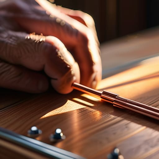

  • How to Build a Dipole That Works First Time

    How to Build a Dipole That Works First Time

    I was standing on a ridge in the Cascades last autumn, shivering in a damp wind, staring at an SWR meter that refused to budge from 3.5:1, even though I’d followed the “standard” math to the letter. I had spent three hours wrestling with wire and insulators, only to realize that the textbook formula for length is a lie if you don’t account for the specific dielectric of your insulators or the actual tension on the line. Most people think learning how to build a dipole is just a matter of cutting two pieces of wire to a specific length and calling it a day, but if you aren’t measuring the actual resonant frequency once it’s in the air, you’re just guessing.

    In this guide, I’m going to skip the academic fluff and show you how to build a dipole that actually performs when the sun goes down. We’re going to talk about real-world variables—like why your height above ground will change your pattern more than the wire gauge ever will—and I’ll show you how to trim for resonance without wasting half your spool of copper. I’m not here to give you a theoretical exercise; I want to give you a reliable antenna that stays tuned even when the wind starts howling.

    Table of Contents

    Guide Overview

    Total Time: 1-2 hours
    Estimated Cost: $20-40
    Difficulty: Beginner

    Tools & Supplies

    • Wire cutters for trimming lengths
    • Measuring tape for precision
    • Insulated copper wire (approx. 20-50 feet)
    • Coaxial cable (length based on antenna size)
    • Electrical tape for securing connections
    • Two connector types (matching your radio/tuner)

    Step-by-Step Instructions

    • 1. First, grab your wire. Don’t bother with anything fancy like copper-clad steel if you’re just starting; a decent length of 14 AWG stranded copper wire is plenty. I prefer stranded because it handles the constant bending and UV exposure of being hung in trees much better than solid core, which eventually just gets brittle and snaps. Measure out your total length based on the frequency you’re targeting, but add about two feet of “oops” room to each end. I’ve learned the hard way that trimming to length is a much easier job than trying to solder more wire onto a stub that’s too short.
    • 2. Once you have your wire, you need to calculate your legs. A standard half-wave dipole is just two equal halves, so divide your total length by two. Use a reliable formula—don’t just eyeball it—and remember that the physical length needs to be slightly longer than the theoretical calculation to account for the end effect. I usually calculate for the bottom end of the band I want to use, because it’s always easier to trim a wire shorter to raise your resonant frequency than it is to try and stretch it out.
    • 3. Now, let’s talk about the center insulator. This is where most people get lazy and use a piece of scrap plastic, but if you want this thing to last more than one season, get a proper polycarbonate center insulator. You’ll need to create a way to attach your feedline here. I like using two small stainless steel eye bolts embedded in the insulator; it gives you a solid, corrosion-resistant point to wrap your coax and keeps the two halves of the dipole from touching and shorting out.
    • 4. Strip your coaxial cable and prepare your connection. If you’re using a standard RG-8X or RG-58, strip back enough jacket to expose the center conductor and the braid. I recommend using a high-quality solderless crimp connector if you have one, but if you’re working from a field kit, a neat, tight wrap of the braid around the insulator’s mounting point works too. Just make sure there isn’t a single stray strand of braid touching that center conductor, or you’ll see a dead SWR the moment you key the mic.
    • 5. Attach your end insulators. You don’t need anything expensive here—even some heavy-duty UV-rated nylon rope can work—but you need something that won’t stretch significantly under tension. Attach an insulator to each end of your wire legs. This is the crucial part where you ensure the wire is held taut but not so tight that you’re stressing the copper to its breaking point. I always leave a little bit of slack at the very ends to account for thermal expansion and contraction.
    • 6. Before you go climbing a tree, you need to test it on the bench. Connect your dipole to an antenna analyzer or your rig’s SWR meter. I don’t care how much you think you know your math; always measure the SWR before you hang it up. If the resonance is too low, trim an inch off each side and check again. If you’re working on a 40-meter band, expect to see a decent pattern, but remember: height is everything. If you test this on the ground, your readings will be garbage because of ground coupling, so try to get it at least 15 or 20 feet up before you start making final adjustments.

    Choosing Your Antenna Element Material for Real Performance

    Choosing Your Antenna Element Material for Real Performance

    When you start looking at wire antenna construction, the first thing people ask is whether they should use copper or aluminum. Honestly, it’s not about the prestige of the metal; it’s about weight and oxidation. I’ve spent years dragging gear up ridges, and if you use thick, heavy copper wire, you’re going to regret it by the time you reach the summit. I usually stick to #14 or #16 AWG stranded copper because it’s supple enough to knot without snapping, but you need to be mindful of how the material affects your electrical length.

    Don’t get caught off guard by the fact that different materials can slightly shift your antenna resonance frequency. If you swap out a heavy-gauge wire for something thinner, your SWR is going to move, and you’ll find yourself chasing a moving target. I always tell people to leave a little extra “slack” in their calculations to account for this. Also, pay attention to your coaxial cable connection; if you use a material that oxidizes easily, like cheap aluminum, that junction becomes a high-resistance mess that will tank your performance regardless of how well you tuned the elements.

    Calculating Antenna Resonance Frequency Without Relying on 1987 Math

    Calculating Antenna Resonance Frequency Without Relying on 1987 Math

    Look, we’ve all seen the formula $468/f$ printed in every handbook since the dawn of the hobby. It’s a decent starting point, but if you treat it as gospel, you’re going to spend more time trimming wire than actually making contacts. That math assumes a theoretical vacuum and perfect conditions, but it doesn’t account for the specific antenna element material you’ve chosen or the way your insulators interact with the environment. I’ve spent too many afternoons on a ridge realizing my “perfect” length was off by three feet because I forgot how much the insulation on my wire actually affects the capacitance.

    When you’re actually out there doing the wire antenna construction, stop trying to be a mathematician and start being an observer. Use an analyzer to find your actual antenna resonance frequency rather than trusting a calculator. My rule of thumb? Cut your wire at least 5% longer than the formula suggests. It is much easier to trim a few inches off to bring the SWR down than it is to try and splice more wire back on when you’ve overshot the mark. Measure twice, trim once, and always leave yourself some breathing room.

    Five Things the Manual Won't Tell You About Your Dipole

    • Stop obsessing over the exact length of the wire and start focusing on your feedline height. I’ve seen a perfectly resonant 20-meter dipole perform like garbage because it was sitting six feet off the ground; get it up to at least 15 or 20 feet if you can, or you’re just wasting your time fighting a high angle of radiation.
    • Use high-quality coaxial, but don’t go overboard on the price just because the box looks pretty. I’ve tested RG-58 against more expensive brands on a simple dipole setup, and unless you’re running a massive run of cable, the signal loss difference is negligible compared to the cost—save that money for a better tuner or a decent tripod.
    • Leave yourself some “tuning slack.” When you’re cutting your elements, don’t cut them to the exact calculated length on the first pass. Cut them about 3% longer than you think you need; it is much easier for me to trim a wire down to hit resonance than it is to try and stretch a wire that’s already too short.
    • Don’t skimp on the balun, but don’t overcomplicate it either. A simple 1:1 current balun at the feed point is non-negotiable if you want to keep RF off your coax and prevent your signal from jumping into your microphone or your computer. I’ve spent too many evenings chasing “phantom” noise that was actually just my own rig feeding back through the shield.
    • Expect the environment to change your results. A dipole that reads perfectly at 10:00 AM in my backyard might shift its resonant frequency by a few kilohertz when I hang it in a damp field or near a cluster of pine trees. If your SWR looks a little wonky, don’t assume you built it wrong—check your surroundings before you start hacking at the wire.

    The Bottom Line Before You Solder

    Stop obsessing over the perfect wire gauge and start worrying about your height; a copper wire at 20 feet will never perform like a silver-plated masterpiece at 5 feet, so plan your mounting before you buy your materials.

    Math gets you in the ballpark, but the real tuning happens when you’re standing there with an SWR meter in your hand; always cut your elements a few inches longer than your calculations suggest so you have room to trim down to resonance.

    Don’t mistake a lucky ionospheric opening for a perfect antenna design; if your SWR is low but you aren’t making contacts, check your ground plane and your height before you go blaming the sun.

    The Truth About the Tuning Process

    You can spend all afternoon tweaking your wire lengths to hit a perfect SWR of 1.1:1, but if you don’t account for the fact that you’re hanging that dipole ten feet lower than your math predicted, you’re just chasing ghosts. A dipole isn’t a math problem you solve once; it’s a physical object that lives in the real world, and the real world has ground planes, nearby trees, and gravity.

    Wren Castellano

    Final Thoughts Before You Hit the Airwaves

    Final Thoughts Before You Hit the Airwaves

    At the end of the day, building a dipole isn’t about following a recipe from a dusty manual; it’s about understanding how your specific materials and your specific environment interact. We’ve covered the math, the materials, and the importance of getting your resonance right, but don’t forget that the most important variable is still the height above ground. You can build the most mathematically perfect wire in the world, but if you hang it too low to a tree branch, you’re going to struggle with a skewed pattern and a high SWR that no tuner can truly fix. Measure your results, keep a log of your SWR under different conditions, and remember that real-world performance often requires a bit of fine-tuning once the wire is actually in the air.

    There is a specific kind of satisfaction that comes from hearing a weak signal break through the noise on an antenna you cut, soldered, and hoisted yourself. It’s a connection to the physics of the medium that you just don’t get from buying a pre-made wire on a spool. Radio is a living, breathing thing—the ionosphere shifts, the weather changes, and your antenna will too. Don’t be afraid to tweak and test until it works. Once you stop fearing the SWR meter and start using it as a tool for discovery, you’ve truly become a radio operator. Now, get that wire up and see who is out there waiting to hear you.

    Frequently Asked Questions

    If I'm building this for a portable setup, how much does the height above ground actually change my SWR if I'm just throwing it over a tree branch?

    Look, if you’re just throwing a wire over a branch, your SWR isn’t going to change much—but your radiation pattern absolutely will. SWR is about the electrical length of the wire, which stays the same whether it’s at ten feet or fifty. However, if that tree branch is low, you’re going to lose your signal into the dirt. I’ve measured dipoles at 15 feet that looked “fine” on the meter but performed like garbage. Get it as high as the branch allows.

    I've seen people using different types of coax for their feedline; is there a real measurable difference in loss for a basic dipole, or is it just something people argue about?

    It’s definitely not just an argument; the physics don’t care about your opinions. If you’re running a 40-meter dipole and using cheap RG-58 for a fifty-foot run, you’re literally burning your signal into the jacket before it even hits the antenna. I’ve measured the difference—switching to an LMR-400 or even a decent RG-8X can drop your line loss by more than half on lower bands. Pick your coax based on your distance and frequency, not the price tag.

    Once I've got the elements cut to my calculated length, how much "trimming room" should I actually leave to account for real-world tuning?

    Look, don’t cut it to the exact millimeter your calculator gave you. If you do, you’re just begging for a headache. I always leave about 10% extra length on each element—call it “tuning insurance.” For a standard 40-meter dipole, that’s roughly 6 to 8 inches of extra wire on each side. It’s much easier to trim a wire that’s slightly too long than it is to find more copper once you’ve undershot the frequency.

  • How to Get Ft8 Working From Scratch

    How to Get Ft8 Working From Scratch

    I remember sitting on a ridge in the Cascades last autumn, staring at a waterfall that looked like nothing but static, wondering why my signal wasn’t hitting anything. I had followed every forum thread to the letter, yet I was getting zero decibels of meaningful contact. Most people will tell you that if you just follow the manufacturer’s checklist, you’re good to go, but that’s a lie. Learning how to set up FT8 isn’t about clicking “OK” on a series of pop-up windows; it’s about understanding the timing and the math happening behind your screen. If your computer clock is off by even a fraction of a second, or if your CAT control is fighting your transceiver, you might as well be shouting into a vacuum.

    In this guide, I’m stripping away the fluff and the “just trust the manual” nonsense. I’m going to show you the actual, measured way to configure your software, from syncing your Windows time to managing your audio levels so you aren’t clipping your signal into oblivion. We’ll talk about why your waterfall looks like garbage even when the bands are open, and I’ll give you the specific settings I use when I’m operating on a tight power budget. No hype, just the settings that actually work when the ionosphere is cooperating.

    Table of Contents

    Guide Overview

    Total Time: 1-2 hours
    Estimated Cost: $0 (assuming existing radio equipment)
    Difficulty: Beginner

    Tools & Supplies

    • WSJT-X Software (The primary decoding program)
    • Computer/Laptop (To run the software and process signals)
    • Sound Card/USB Interface (To connect radio audio to computer)
    • HF Radio Transceiver (1 unit)
    • Antenna System (1 unit)
    • USB Cable (1 unit)

    Step-by-Step Instructions

    • 1. First, stop thinking about your radio and start thinking about your computer’s clock. FT8 is a timing-sensitive protocol; it doesn’t care about your signal strength if your time is off by even a few hundred milliseconds. I’ve sat there watching a perfect signal fail to decode simply because the user was relying on the standard Windows time sync, which can drift. Download a dedicated NTP client like Dimension 4 or use the built-in time sync in your software, and make sure you are pulling from a reliable stratum-1 server. If your time isn’t rock solid, you’re just making noise.
    • 2. Next, you need to get your signal path sorted through a virtual audio cable (VAC). You aren’t going to be plugging a physical 3.5mm jack from your transceiver into your soundcard like it’s 1995—unless you want a massive amount of ground loop noise. Install a driver like VB-Audio Cable to create a digital bridge between your transceiver’s interface (like a SignaLink or a built-in USB soundcard) and your FT8 software. When you test this, watch your input levels; you want your received signal to be loud enough to see on the waterfall, but not so hot that you’re clipping the ADC.
    • 3. Now, let’s talk about the CAT control setup. You need your computer to be able to tell your radio what frequency it’s sitting on, otherwise, the software is flying blind. Go into your transceiver’s menu and ensure the CAT settings—baud rate, parity, and stop bits—match exactly what you’ve entered into WSJT-X. I’ve lost more evenings than I care to admit because someone had the baud rate set to 9600 on the radio but 4800 in the software. If the frequency readout in your software isn’t moving when you turn the dial on the rig, you haven’t finished this step.
    • 4. Once the communication is established, you have to configure your audio input and output levels. This is where most people blow their chance at a good contact. Open the WSJT-X settings and look at the audio tab. You want to adjust your radio’s ALC (Automatic Level Control) so that when you transmit, you are hitting the band with a clean signal but not driving the amp into saturation. If your waveform looks like a square wave instead of a sine wave, you are distorting the signal, and the guys on the other end won’t be able to decode you regardless of how much power you’re throwing at them.
    • 5. Set your operating frequency and mode with an eye on the current propagation. Don’t just pick a frequency because it’s “the FT8 frequency.” Check a real-time propagation tool or a DX cluster to see where the openings actually are. If you’re working 20 meters, make sure your software is set to the correct sub-band. I’ve seen people try to force a contact on a frequency that was actually part of a sideband, and it’s a complete waste of electricity.
    • 6. Finally, do a test decode before you start trying to hunt DX. Find a local station or a high-signal repeater and see if you can grab a decode. If you see nothing on the waterfall but a mess of static, go back to step two and check your gain. If you see the signal but it won’t decode, go back to step one and check your clock. I don’t care how much money you spent on your rig; if your setup isn’t synchronized, you’re just a very expensive source of interference.

    Mastering Wsjt X Configuration Settings and Cat Control Setup

    Mastering Wsjt X Configuration Settings and Cat Control Setup

    Once you’ve got the basics down, the real headache usually starts with the handshake between your computer and your rig. I’ve spent more nights than I care to admit staring at a waterfall that refuses to move because the CAT control setup for amateur radio was slightly off. It isn’t enough to just plug in a USB cable; you need to ensure your COM port settings and baud rates actually match what your radio expects. If your frequency isn’t jumping when you click the software, don’t assume the cable is broken—check your driver settings first.

    Then there’s the audio. Most people think “more is better,” but if you’re slamming the input, you’re just creating digital clipping that makes your signal look like a square wave to everyone else. I spend a lot of time optimizing audio input levels so that the signal sits comfortably in the sweet spot of the waterfall without hitting the red. If you’re seeing decent signal reports but your decodes are failing, stop looking at the ionosphere and start looking at your audio gain. A clean, slightly lower signal will beat a loud, distorted mess every single time.

    Optimizing Audio Input Levels and Correcting Gps Time Sync Errors

    Optimizing Audio Input Levels and Correcting Gps Time Sync Errors

    Once you’ve got your CAT control behaving, the next thing that’ll trip you up is your audio chain. I’ve spent too many evenings staring at a waterfall that looks like a jagged mess because the input gain was cranked to hell. When optimizing audio input levels, don’t just trust the slider in WSJT-X. I prefer to look at the actual waveform in a separate analyzer or use the built-in levels to ensure you aren’t clipping. If your signal is hitting the digital side too hard, you’re essentially adding noise to your own transmission. Aim for a clean, consistent level; it’s better to be a hair too quiet than to drown your signal in harmonic distortion.

    Then there’s the time issue. If you aren’t using a dedicated GPS clock, you’re playing a dangerous game. I’ve seen plenty of beginners get frustrated with FT8 signal decoding troubleshooting only to realize their computer clock drifted by a few milliseconds. Even a tiny discrepancy makes the software think the signal is coming from a different time slot, and suddenly, you’re shouting into the void. Correcting GPS time sync errors isn’t just a “pro tip”—it’s the difference between a successful contact and a wasted night.

    Five Things the Manual Won't Tell You About Getting a Clean FT8 Signal

    • Watch your PTT offset like a hawk. If you’re seeing your own signal bleeding into your receive path, or if the waterfall shows a smear right where your signal should be, your CAT control isn’t talking to your rig correctly. I’ve spent too many evenings chasing “bad propagation” only to realize my radio was still transmitting for 200 milliseconds after the software thought it had stopped.
    • Stop aiming for “loud” and start aiming for “clean.” I see people cranking their USB audio levels until the waveform looks like a solid brick. That’s just digital clipping, and it’s the fastest way to ensure nobody can decode you. Set your levels so you have actual headroom; I’d rather have a slightly quieter signal that is mathematically precise than a loud one that’s just noise.
    • Check your frequency stability before you commit to a session. If you’re using an older rig without a temperature-compensated crystal oscillator (TCXO), your frequency might drift significantly as the radio warms up. If your offset is drifting by even a few hertz during a session, the WSJT-X decoding window won’t catch you, and you’ll be left staring at a blank waterfall.
    • Don’t ignore the “noise floor” reality. If you’re operating from a suburban backyard with high local RF interference, your FT8 settings won’t save you. I always check my local noise floor on the waterfall before I even think about hitting ‘transmit.’ If the floor is sitting too high, no amount of software tweaking is going to pull a weak signal out of the muck.
    • Your GPS sync isn’t just a suggestion; it’s the backbone of the whole thing. If your computer’s system clock is off by even a second, the timing windows for the FT8 packets will miss each other entirely. If you aren’t using a dedicated GPS dongle or a highly accurate NTP sync, you’re basically throwing messages into a dark room and hoping someone is looking in the right direction at the exact right millisecond.

    The Bottom Line: Don't Let the Software Do All the Thinking

    If your waterfall looks like a mess of noise, stop blaming the ionosphere and check your audio levels; you’re likely overdriving your input and clipping the signal before it even hits the decoder.

    CAT control and GPS sync aren’t “set and forget” luxuries—if your timing is off by even a fraction of a second, you’re just shouting into the void and wasting your evening.

    Real-world FT8 success comes down to the math, not the manual; measure your offsets, verify your signal chain, and remember that a perfectly configured rig won’t save you if your antenna is sitting too low to the ground.

    Beyond the Manual

    You can spend all night tweaking your WSJT-X settings, but if your rig’s internal clock is drifting or your audio is clipping the input, you’re just shouting digital noise into a void. Stop chasing the software’s “recommended” defaults and start looking at your actual signal levels; if your waterfall doesn’t look clean, the problem isn’t the ionosphere, it’s your setup.

    Wren Castellano

    Don't Let the Software Do All the Thinking

    Don't Let the Software Do All the Thinking

    At the end of the day, setting up FT8 isn’t about checking off a list of boxes in WSJT-X; it’s about understanding the signal chain from your computer’s clock to the actual copper in your antenna. We’ve covered the essentials—getting your CAT control to talk to your rig without a fight, dialing in those audio levels so you aren’t clipping your waterfall, and ensuring your GPS sync is tight enough that you aren’t chasing ghosts. If you’ve done it right, your setup should be a transparent window into the band, not a source of technical friction. Remember, if your decodes look messy even with “perfect” settings, look at your hardware first. A software tweak won’t fix a noisy power supply or a poorly grounded transceiver.

    Once the configuration is settled, the real fun begins. There is a specific kind of quiet magic in watching those little callsigns drift onto your screen during a period of mediocre propagation, knowing that your station is tuned exactly where it needs to be. Don’t get discouraged if you don’t hit a DX station on your first night; sometimes the ionosphere just needs a moment to settle. Just keep your levels steady, keep your eyes on the waterfall, and trust your measurements more than the manual. Now, get off the computer screen and go see what the bands are actually doing.

    Frequently Asked Questions

    I’ve got my levels set, but why am I still seeing nothing but noise on the waterfall even when the signal strength says I should be decoding?

    If your levels look right but the waterfall is just static, stop looking at your software and start looking at your rig. Most of the time, you’re being swamped by local RFI or a poorly filtered power supply. If you’re seeing a thick floor of noise instead of clean gaps, your receiver’s dynamic range is being eaten alive. Check your PTT/CAT timing, too—if the software thinks you’re transmitting when you aren’t, you’ll just see ghosts.

    My CAT control keeps losing sync every time I change bands; is this a software glitch or am I missing a driver step?

    It’s rarely a “glitch,” and it’s usually a handshake problem. If your CAT loses sync during a band change, your rig is likely struggling to keep up with the polling rate you’ve set in WSJT-X. I’ve seen this happen constantly when the polling interval is too aggressive for the USB-to-Serial driver to handle. Slow down your CAT polling rate to 500ms or 1000ms. If that doesn’t fix it, check your driver version; the generic Windows ones are notoriously flaky for real-time control.

    Does it actually matter if I use a dedicated soundcard versus the built-in USB audio on my rig, or is that just more gear for the sake of gear?

    It’s not just gear for gear’s sake, but you don’t need a $500 studio interface to get started. I’ve tested both. The built-in USB audio on most modern rigs is fine for casual use, but the noise floor is often higher due to internal switching power supplies. If you’re chasing those weak signals at -22 dB, a dedicated, shielded soundcard will give you a cleaner waterfall. If your built-in audio sounds “fuzzy,” it’s the hardware, not the ionosphere.

  • How to Solder Properly, and Why Your Joints Look Like That

    How to Solder Properly, and Why Your Joints Look Like That

    I spent my first year in the lab thinking that more heat meant a better connection, only to watch a perfectly good $50 PCB turn into a blackened, delaminated mess because I was trying to “force” the solder to melt. Most of the tutorials you find online make it look like magic—just touch the tip to the joint and poof, a perfect shiny bead appears. But if you’re struggling with cold joints that crack the moment you move a wire, or solder that beads up like water on a waxed car, you haven’t actually learned how to solder properly yet; you’ve just learned how to melt metal.

    In this guide, I’m stripping away the fluff and the “magic” tricks to show you the actual physics of a good joint. I’ll walk you through why your iron temperature matters more than the brand name on the box, how to manage your flux like a professional, and how to recognize a solid mechanical and electrical bond versus a failure waiting to happen. No textbook jargon, just the practical reality of what works when you’re sitting at a cluttered workbench at 11:00 PM.

    Table of Contents

    Guide Overview

    Total Time: 1-2 hours
    Estimated Cost: $40-80
    Difficulty: Beginner

    Tools & Supplies

    • Soldering iron (adjustable temperature preferred)
    • Soldering stand (to prevent burns and fires)
    • Desoldering pump or wick (for correcting mistakes)
    • Sponge or brass cleaner (to clean the iron tip)
    • Solder wire (60/40 leaded or lead-free rosin core)
    • Flux (paste or pen to aid flow)
    • Solder wick (copper braid for removing excess)

    Step-by-Step Instructions

    • 1. First, stop treating your iron like a heating element and start treating it like a precision tool. If you’re using one of those cheap, unbranded sticks from a bargain bin, do yourself a favor and toss it. You need a station with adjustable temperature control. I usually set mine between 330°C and 370°C depending on the solder weight, but the point is you need to be able to dial it in. If you’re working on a delicate SDR module, you don’t want to cook the traces; if you’re tacking together heavy-gauge wire for a field antenna, you need the thermal mass to actually get the job done.
    • 2. Clean your tip before you even think about touching a component. I don’t care how shiny it looks; if there is a layer of oxidized carbon on it, you aren’t transferring heat, you’re just fighting physics. Use a brass sponge rather than a wet sponge if you can. Wet sponges cause thermal shock that can micro-crack your heating element over time, and they leave the tip too cold. You want a tip that is bright, shiny, and tinned with a fresh layer of solder before it ever meets the board.
    • 3. Now, here is where most people mess up: you don’t just melt solder onto the iron and hope it flows. That’s how you get cold joints that fail the moment you move the rig. You have to heat the joint, not the solder. Touch the tip of the iron so that it makes contact with both the copper pad and the component lead simultaneously. Hold it there for a second or two until the metal components themselves are hot enough to melt the solder on contact.
    • 4. Once the pad and the lead are actually hot, feed the solder into the junction, not directly onto the iron tip. If you do it right, the solder will wick into the hole and wrap around the lead via capillary action. It should look like a smooth, concave fillet—kind of like a tiny silver volcano. If it looks like a round, dull bead, you didn’t get enough heat into the pad, and that joint is going to crack the first time you vibrate your radio gear in a backpack.
    • 5. Don’t be impatient. I see people pulling the iron away while the solder is still moving, which is a one-way ticket to a cold solder joint. You have to wait for the solder to solidify completely before you move the component or remove the heat. If you move it even a fraction of a millimeter while it’s in that “plastic” phase, the crystalline structure won’t form correctly, and you’ll end up with a high-resistance connection that’s a nightmare to troubleshoot later.
    • 6. Finally, give it a quick inspection with a magnifying glass—or your eyes, if you’ve got the patience. A good joint should be bright and shiny. If it looks grey, grainy, or “frosty,” you either overheated it or didn’t provide enough heat to begin with. If you see a bridge where solder is touching two adjacent pads, don’t try to scrape it off with a knife. Use your solder wick to draw the excess away, then re-flow it properly. It’s much easier to do it right the second time than to try and fix a messy board later.

    Mastering Solder Wetting and Flow for Real Results

    Mastering Solder Wetting and Flow for Real Results

    If you’ve followed the steps but your joints still look like dull, grey pebbles instead of shiny, concave ramps, you aren’t actually seeing proper solder wetting and flow. Wetting is the physical phenomenon where the liquid solder actually bonds to the metal surface through capillary action. If it’s just sitting on top like a bead of water on a waxed car, you haven’t achieved a molecular bond. This usually happens because you’re either underheating the pad or your tip is oxidized. I’ve spent too many nights troubleshooting field repairs only to realize the “fix” was just a lack of thermal mass. You have to heat the joint, not just the wire, to ensure the heat travels through the component lead into the pad itself.

    Don’t skip your soldering iron tip maintenance either. A blackened, crusty tip is a thermal insulator, and it will lie to you; it might feel hot, but it won’t transfer energy where it needs to go. I keep a brass sponge and some high-quality tip tinner on my bench because a clean tip is the difference between a reliable connection and a nightmare of preventing cold solder joints later on. If the solder doesn’t flow instantly when it hits the junction, pull back, clean the tip, and try again.

    Preventing Cold Solder Joints and Other Common Failures

    Preventing Cold Solder Joints and Other Common Failures

    The biggest mistake I see in the workshop isn’t a lack of skill; it’s impatience. You’ll see someone holding the iron to a pad, seeing the solder melt, and pulling away before the heat has actually soaked into the component lead and the copper trace. That’s how you end up preventing cold solder joints in theory but failing in practice. A cold joint might look okay to the naked eye, but it’s structurally brittle and electrically noisy. If the joint looks dull or grainy instead of having that smooth, satin sheen, you didn’t get enough thermal mass into the connection. You didn’t just miss the mark; you created a high-resistance bottleneck that will eventually fail when the gear vibrates or gets warm.

    If you find yourself constantly fighting a joint that won’t take, stop blaming the solder and look at your iron. Proper soldering iron tip maintenance is non-negotiable. A blackened, oxidized tip acts like an insulator rather than a conductor; it won’t transfer heat, no matter how high you crank the temperature. I’ve spent more hours than I care to admit cleaning tips with brass wool and re-tinning them just to get a decent flow again. If your tip looks like charcoal, you aren’t soldering; you’re just waving a hot stick around.

    Five Ways to Stop Making Messy Joints and Start Making Connections

    • Clean your pads like you mean it. I’ve seen people try to solder onto oxidized copper or traces covered in finger oils, and it’s like trying to glue two pieces of ice together. If you aren’t using a bit of isopropyl alcohol or a dedicated flux cleaner before you touch the iron to the board, you’re just fighting physics from the start.
    • Don’t treat the solder like it’s the heat source. The iron provides the thermal energy, but the solder is just the filler. If you’re just melting a blob of solder onto the tip of your iron and then “painting” it onto the joint, you’re going to end up with a cold joint every single time. Heat the pad and the component lead simultaneously, then let the solder flow into the gap on its own.
    • Use the right flux, not just whatever came in the spool. Most hobbyist solder has a tiny bit of rosin core, but for anything remotely serious—especially when you’re working on older gear or rebuilding a radio’s power stage—you need dedicated flux. It breaks the surface tension and lets the solder actually “wet” the metal instead of just sitting there like a bead of water on a waxed car.
    • Watch the clock, not just the temperature. I’ve seen too many beginners hold a hot iron against a delicate PCB trace for thirty seconds because they’re nervous. You aren’t “making sure it’s hot enough”; you’re delaminating the board and cooking the adhesive. If the solder hasn’t flowed within three to five seconds, pull back, let it cool, and rethink your thermal strategy.
    • Learn the visual cue of a “bright” joint. A good solder joint should look shiny and concave, like a tiny silver volcano. If it looks dull, grainy, or like a grey lump of clay, it’s a failure. Even if the multimeter says there’s continuity, a dull joint is a high-resistance joint, and in an RF circuit, that’s just a glorified heater that’s going to drift your tuning or fail when the temperature shifts.

    The Bottom Line for Your Workbench

    Stop chasing the heat; if you aren’t seeing the solder flow like liquid silver across the pad in under two seconds, you aren’t actually soldering, you’re just cooking the flux into a useless crust.

    Cleanliness isn’t a suggestion—if your copper looks dull or has a layer of oxidation, no amount of expensive leaded solder is going to save you from a high-resistance joint that fails the first time the gear gets warm.

    Trust your eyes over your theory; a good joint should be concave and shiny, and if it looks like a grey, grainy bead of solder, pull the iron away and do it again before you call it finished.

    ## The Truth About the Joint

    If you’re staring at a joint that looks like a dull, grey bead of wax instead of a shiny, concave fillet, stop what you’re doing; you haven’t “finished” the solder, you’ve just dumped a lump of metal on a board that isn’t ready to hold it.

    Wren Castellano

    Beyond the Solder Joint

    Mastering heat Beyond the Solder Joint.

    At the end of the day, good soldering isn’t about following a recipe from a textbook; it’s about respecting the physics of heat transfer. You’ve learned that if you aren’t managing your temperature or cleaning your pads, you’re just asking for a failure down the line. Remember that a successful joint is defined by proper wetting and a smooth, concave fillet—not just by whether the component stayed attached while you were shaking the board. If you’ve been seeing dull, grainy surfaces or components that look like they’re just sitting on top of the copper rather than being bonded to it, you haven’t mastered the heat yet. Keep your iron clean, keep your flux active, and stop rushing the process just to get to the next step.

    There is a specific kind of satisfaction that comes from looking at a finished PCB and knowing every single connection is rock solid. In a world where everything is increasingly disposable and “black-boxed,” there is something deeply grounding about being able to open a device, find a fault, and actually fix it yourself. Whether you are repairing a vintage transceiver or building a custom antenna tuner for your next portable excursion, these skills are what turn you from a consumer into a maker. Don’t get discouraged by the occasional bridged joint or a messy pad; even I still have days where my hands aren’t as steady as they used to be. Just keep measuring, keep practicing, and trust the physics.

    Frequently Asked Questions

    My iron is set to 350°C but the solder still looks like dull, grainy sand instead of shiny silver; am I using the wrong flux or is my iron just not actually hitting the temperature it says?

    If it looks like grainy sand, you’re dealing with a classic case of insufficient heat or oxidized surfaces. At 350°C, you should be seeing flow, but if your iron’s thermocouple is lying to you—and they often do—you’re just sitting there cooking the flux without actually wetting the metal. Try bumping it to 370°C. If it still won’t shine, clean your tip or check your solder; cheap, unfluxed wire is a nightmare.

    Is there a point where using lead-free solder becomes more of a headache than it's worth for small, delicate RF components?

    If you’re working on high-frequency RF traces or tiny SMD components, yes, lead-free can absolutely be a headache. It requires higher heat and much more aggressive flux to get that reliable wetting I was talking about. For delicate boards where you’re worried about lifting pads or thermal shock, I still reach for 63/37 tin-lead. It flows predictably and stays liquid longer, giving you that crucial window to fix a mistake before the joint freezes.

    When I'm working on a tight PCB with components packed close together, how do I stop the solder from bridging without making a mess of the pads?

    When you’re dealing with high-density boards, stop trying to “aim” the solder. That’s how you get bridges. Instead, treat the iron and the solder as two separate tools. Use a fine-tipped chisel iron to heat the pad and the lead simultaneously, then feed the solder into the joint, not the iron. If you’re still struggling, grab some tacky flux. It’s not cheating; it’s physics. The flux pulls the molten metal onto the metal, not the gaps between.

  • How to Choose a First Hf Radio Without Overbuying

    How to Choose a First Hf Radio Without Overbuying

    Stop listening to the guys in the forums who swear you need a $3,000 transceiver just to hear a signal through the noise. I’ve spent twenty years designing front ends and sitting on damp hillsides, and if there’s one thing I’ve learned, it’s that most of the “essential” gear lists you see online are just expensive ways to solve problems you don’t actually have. When you start researching how to choose your first hf radio, you’re going to run into a wall of marketing fluff and outdated advice from people who haven’t measured a signal-to-noise ratio since the Reagan administration. It’s frustrating, it’s expensive, and frankly, it’s unnecessary.

    I’m not here to sell you a dream or push a specific brand just because they have a shiny logo. My promise to you is simple: I will give you the unvarnished truth based on actual measurements and real-world operating. We’re going to look at what actually matters—receiver sensitivity, bandwidth, and how a rig handles a messy antenna—without the hype. If a radio is a waste of your hard-earned money, I’ll tell you, and if a budget rig performs like a champ under the right conditions, you’ll be the first to know.

    Table of Contents

    Dont Waste Money on Overpriced Entry Level Ham Radio Gear

    Dont Waste Money on Overpriced Entry Level Ham Radio Gear

    Look, I like the big manufacturers as much as the next person, but don’t let a shiny marketing brochure trick you into buying a rig that’s overpriced just because it has a familiar logo on the front. When you’re looking at entry level ham radio gear, you’ll notice a massive price gap between “budget” rigs and “premium” ones. Often, that gap isn’t going toward better receivers or lower noise floors; it’s going toward a fancy touchscreen or a chassis that looks good on a desk. If you’re just starting out, you don’t need a $2,000 machine to learn the ropes. You need something with a decent dynamic range and a tuner that doesn’t give up the ghost the moment your antenna isn’t perfectly resonant.

    I’ve seen too many newcomers get caught in the trap of choosing an expensive hf transceiver vs base station setup before they even know if they prefer CW or SSB. If you’re planning on being portable—which, if you follow my lead, you should be—don’t sink your entire budget into a heavy, power-hungry desktop unit. Buy a mid-range rig that actually performs, and take the money you saved to buy a better power supply or a decent antenna tuner. Measure twice, buy once.

    Hf Transceiver vs Base Station What the Manuals Wont Tell You

    Hf Transceiver vs Base Station What the Manuals Wont Tell You

    The brochures will try to blur the lines between a compact transceiver and a dedicated base station, but they’re two different animals. A transceiver is built for mobility—think lighter chassis, maybe a smaller display, and a focus on being “good enough” for a variety of settings. It’s fine for a desk, but the moment you try to push it, you’ll see the compromises. When I’m out on a ridge, I want a transceiver because I can carry it, but I’m not expecting it to drive a massive, high-power amplifier without sweating.

    The real issue is how they handle the workload. A true base station setup is designed to sit there, connected to a heavy-duty power supply and a permanent antenna system that isn’t going anywhere. When comparing hf transceiver vs base station setups, you have to look at the thermal management and the stability of the internal oscillator. If you’re planning on spending hours in CW or digging weak signals out of the noise, a budget transceiver might start drifting once it gets warm. Don’t mistake portability for versatility; if you want to sit in a comfortable chair and work the world, build for a station, not a backpack.

    Five Things to Check Before You Swipe Your Card

    • Look at the actual receiver performance, not just the “wattage” on the box. A 100-watt rig is a paperweight if the dynamic range is so poor that a single nearby station wipes out the weak signal you’re actually trying to hunt. I’ve sat in the dirt with rigs that had plenty of power but couldn’t pull a signal out of a noisy floor to save their lives.
    • Check the interface options. If you aren’t planning on spending your entire life turning physical knobs—and let’s be honest, most of us eventually want to use a computer or a tablet—make sure the rig has decent USB connectivity or at least a robust CAT control implementation. Don’t get stuck in 1985 because the manufacturer decided “modern connectivity” was an optional luxury.
    • Don’t ignore the tuner situation. You can buy a rig with a built-in antenna tuner, but don’t assume that’s the end of your story. I always recommend having an external tuner in your kit, especially if you’re planning to move away from a perfect dipole and start throwing wires up in trees or on hills. A built-in tuner is a convenience; a good external tuner is a necessity.
    • Verify the build quality of the connectors and the cooling. I’ve seen “entry-level” rigs where the chassis feels like it was made from a recycled soda can and the cooling fan sounds like a jet engine taking off. If you’re going to be operating in a shack that gets warm, or if you’re lugging gear into the field, you want something that won’t thermal throttle the moment you try to work a DX station.
    • Figure out your real operating environment before you commit. If you’re building a dedicated shack, a heavy desktop rig is fine. But if you have even a slight itch to take your gear outside, look at the footprint and the power requirements. There is nothing more frustrating than buying a beautiful, heavy piece of gear only to realize it requires a dedicated 20-amp circuit and a custom-built desk just to turn it on.

    The Bottom Line Before You Swipe Your Card

    Stop chasing specs on a page; a radio is only as good as the signal it can actually pull out of the noise, so prioritize receiver sensitivity and dynamic range over a fancy color touchscreen.

    Don’t get trapped in the “all-in-one” lie—if you’re buying a portable rig, make sure the power draw won’t kill your battery bank in twenty minutes, and if you’re going base station, ensure you have the bench space for the actual test gear you’ll need to tune it.

    Budget for the antenna and the feedline first, not the radio; I’ve seen more money wasted on mediocre transceivers paired with junk wires than I have on high-end rigs running well-tuned, properly elevated dipoles.

    The Real Metric of Success

    Stop looking at the feature list on the box and start looking at the signal-to-noise ratio in your actual backyard; a high-end rig with a cheap, poorly mounted antenna is just an expensive way to listen to static, but a modest transceiver paired with a well-placed wire can pull DX out of the ether when the ionosphere actually decides to cooperate.

    Wren Castellano

    The Bottom Line

    Choosing your first HF rig: The Bottom Line.

    At the end of the day, choosing your first HF rig isn’t about finding the most expensive box with the most buttons; it’s about matching the hardware to your actual life. If you’re planning to sit in a dedicated shack, get a base station with decent thermal management. If you’re like me and want to drag your gear up a ridge to see what the view looks like, prioritize weight and power efficiency. Remember that a transceiver is only as good as the antenna you feed it, and no amount of high-end circuitry will compensate for a poorly placed wire or a lack of ground plane. Don’t get distracted by the marketing fluff—look at the actual specs, check the build quality, and buy for your intended use, not for a version of yourself that doesn’t exist yet.

    Once you finally make that first contact—the one where the signal is weak, the noise floor is high, and the ionosphere is being particularly difficult—you’ll realize that the gear is just the tool. The real magic is in the connection you’ve made through the ether. Radio is one of the few places left where you can truly understand the physics of what is happening between your antenna and a station halfway across the world. So, stop overthinking the perfect setup, get something reliable, and get on the air. The bands are waiting, and I promise, the first time you hear a voice through the static, it’s worth every penny.

    Frequently Asked Questions

    Should I prioritize a radio with a built-in antenna tuner, or is it better to invest that money into a dedicated external tuner and better coax?

    Look, if you’re planning to stay at a desk, a built-in tuner is fine. But if you want to actually use the radio, buy the external tuner and better coax. Internal tuners are often just glorified impedance matching circuits that struggle when your antenna isn’t perfectly resonant. An external tuner gives you more headroom and better stability, especially if you’re working with wire antennas at low heights. Spend the money on the tuner; your SWR will thank you.

    Does a high-end SDR-based transceiver actually offer a measurable advantage over a traditional analog rig when I'm working in noisy conditions?

    Look, the marketing says SDRs have “infinite dynamic range,” but that’s a theoretical number that doesn’t account for your local noise floor. In my testing, a high-end SDR-based rig shines when you’re hunting weak signals in a clean environment because of that superior selectivity. But if you’re working in a noisy urban area, a well-built analog rig with a robust front end often holds its own better. It’s not magic; it’s just how the filters handle the garbage.

    If I plan on doing a lot of portable operating, how much weight am I realistically going to sacrifice for a radio that actually has a decent receiver?

    You’re going to feel it in your shoulders. If you want a receiver that can actually pull a signal out of the noise rather than just amplifying the local interference, you’re looking at a weight penalty. A lightweight QRP rig is great for a quick summit, but you’ll sacrifice dynamic range and filtering. Realistically, expect to carry an extra 1.5 to 2 kilograms for a radio with a decent front end. It’s a trade-off between your knees and your signal-to-noise ratio.

  • How to Get Your First Amateur Radio Licence

    How to Get Your First Amateur Radio Licence

    I remember sitting in the corner of my local club back when I was fifteen, surrounded by men who treated the technician exam like it was some sacred, impenetrable ritual. They’d pass around these thick, outdated manuals filled with dense jargon that felt more like a barrier than a bridge, making you think that learning how to get a ham radio licence required a PhD in physics just to touch a microphone. Most of that “wisdom” is just old-timers repeating things they heard in 1987 without ever actually checking the math. It’s frustrating because they make the barrier to entry feel unnecessarily high, when really, you just need to understand the fundamentals and stop overcomplicating the basics.

    I’m not here to feed you that academic fluff or sell you a $50 study guide that’s stuck in the previous decade. Instead, I’m going to give you a practical, data-driven roadmap that cuts through the noise. I’ll tell you exactly what you need to know to pass your exam, which study tools are actually worth your time, and where the real fun begins once you’re on the air. No hype, no gatekeeping—just the straight truth on getting you licensed and onto the bands.

    Table of Contents

    The Data Driven Roadmap to Your Radio Operator Certification Requirements

    The Data Driven Roadmap to Your Radio Operator Certification Requirements

    First, let’s clear the air: you aren’t just memorizing trivia to pass a test; you are learning the legal framework that keeps the airwaves from turning into a chaotic mess of interference. In the US, the FCC amateur radio regulations dictate exactly what you can and cannot do, from how much power you can pump into a dipole to how you must identify your station. Most people dive into a generic ham radio technician class study guide and get bogged down in the minutiae of rules they won’t use for years. I suggest a different approach: focus on the physics of the signals first, then layer the legalities on top. Once you understand why a frequency is restricted, the rules actually start to make sense.

    Don’t waste your time on low-quality, outdated materials. If you’re looking for the most efficient path toward getting your amateur radio callsign, use reputable online ham radio practice tests that mimic the actual exam environment. I’ve seen too many people fail because they studied from a manual written before the digital age changed how we interact with the spectrum. Treat the exam like a technical baseline—once you clear it, the real learning begins when you’re actually out there measuring SWR and chasing DX.

    Why Your Ham Radio Technician Class Study Guide Needs More Math

    Why Your Ham Radio Technician Class Study Guide Needs More Math

    Most of the standard ham radio technician class study guide material you’ll find online reads like a grocery list of definitions. They’ll tell you what a frequency is, or what a wavelength is, but they rarely tell you how they actually dance together. If you just memorize that $c = f lambda$ without understanding the relationship, you’re going to struggle the moment you try to build something that actually works. I’ve seen too many new operators pass their exams only to stand in their backyard staring at a wire, wondering why their SWR is through the roof because they didn’t realize their math was off by a factor of ten.

    You don’t need a PhD, but you do need to move past rote memorization. When you’re working through online ham radio practice tests, don’t just look for the right answer; look for the logic behind it. If you understand the math, you aren’t just guessing which frequency to use—you’re predicting how that signal will behave. Math is the difference between being someone who just pushes buttons and being someone who actually operates a station.

    Stop memorizing and start measuring: 5 ways to actually pass your exam

    • Stop treating the question pool like a list of random facts to memorize; it’s a logic puzzle. If you understand how a frequency relates to a wavelength, you won’t need to memorize the specific math for the exam—you’ll just see the answer.
    • Don’t just buy the first $40 study guide you see on Amazon. Most of them are just glorified lists of answers. Look for materials that explain the why behind the regulations, or you’ll find yourself staring at a question about frequency allocation feeling like you’ve never seen the word before.
    • Find a local club, but don’t just go for the social aspect. Find the person who has been operating since the days of vacuum tubes and ask them to explain the concept of “ground” to you. Most people fail because they think “ground” is just a wire, but in radio, it’s everything.
    • Practice with a real simulator, not just flashcards. You need to get used to the pressure of the timer and the way the questions are phrased. I’ve seen plenty of people who know the material but freeze up because they aren’t used to the actual testing interface.
    • Ignore the “gear hype” while you’re studying. You do not need a $2,000 SDR or a high-end transceiver to pass a written exam. Save your money for the actual antenna components and feedlines once you’ve got the license in hand—that’s where the real physics starts to matter.

    The bottom line on your certification journey

    Stop memorizing old study guides like they’re scripture; focus on understanding how frequency, power, and propagation actually interact, or you’ll be staring at a SWR meter you don’t know how to read.

    Don’t let the “math anxiety” hold you back—you don’t need a PhD, but you do need to be able to handle basic ratios and decimal points if you ever want to build something that actually works instead of just guessing.

    Treat your license as a technical foundation, not a finish line; the exam gets you on the air, but real-world testing and measurement are what actually make you an operator.

    Stop Memorizing, Start Understanding

    Most people approach the exam like they’re studying for a history test, just memorizing dates and definitions to pass a hurdle. But if you want to actually use the radio instead of just owning a piece of expensive desk clutter, you need to stop treating the study guide like a list of facts and start treating it like a manual for how the world actually works.

    Wren Castellano

    Moving Beyond the Manual

    Moving Beyond the Manual for amateur radio.

    Look, getting your license isn’t just about memorizing a list of frequency ranges or memorizing the ITU prefixes just to pass a multiple-choice test. If you actually want to build something that works, you need to understand the underlying physics of why those answers matter. We’ve covered the roadmap from the technician level up to general, and we’ve dismantled the myth that you can just wing the math. Don’t fall into the trap of treating the study guide like a religious text; treat it like a baseline. Use the data, understand the relationship between wavelength and antenna height, and stop relying on folklore that hasn’t been verified since the era of vacuum tubes.

    Once you finally get that callsign in your hand, the real work begins. You’ll find yourself standing on a ridge at dusk, watching an SWR meter dance, wondering if your signal is actually getting out or if the ionosphere is just doing you a massive favor. That uncertainty is exactly where the fun lives. Radio is one of the few remaining disciplines where you can actually touch the medium you’re working with. So, go pass your exam, buy a rig that’s actually worth the copper in its traces, and get out into the field. I’ll see you on the air.

    Frequently Asked Questions

    Do I really need to master the math for the Technician exam, or can I just memorize the formulas to pass?

    Look, if you just want the piece of paper, you can memorize the formulas. The exam board isn’t going to fail you for not understanding the derivation of Ohm’s Law. But here’s the reality: memorizing a formula is useless the second you’re standing in a field trying to figure out why your SWR is spiking. If you don’t understand the relationship between voltage and current, you aren’t building a radio station—you’re just following a recipe.

    Is it worth the extra study time to go straight for General, or should I start with Technician and upgrade later?

    Look, if you have the time to sit with the math now, go for General. I’ve seen too many people get stuck in the Technician rut, thinking they’ll “upgrade later,” only to realize they’ve spent three years playing in the VHF/UHF sandbox while the HF bands were calling. If you want to actually talk to someone halfway across the world—and not just the guy three towns over—you need those HF privileges. Don’t settle for less if you can help it.

    If I'm planning on doing portable operating or SOTA, which license class actually gives me the bands I'll need?

    If you’re looking at SOTA or just hiking a hill for a weekend, don’t settle for the Technician class. You’ll be stuck on the 2-meter band, and let me tell you, trying to work a DX station on VHF from a portable wire antenna is a recipe for frustration. You need at least General class access. Having those HF bands—especially 20 and 40 meters—is the difference between a successful summit and just staring at a silent waterfall.